[BUILD] 1176LN Rev D DIY

GroupDIY Audio Forum

Help Support GroupDIY Audio Forum:

This site may earn a commission from merchant affiliate links, including eBay, Amazon, and others.
Are you building an 1176?  Check the MNATs wiring page again.  You need to have a center tap secondary as I described regardless of you local mains.  Also your primary needs to be in SERIES for 240V.
 
Have a look at the image in the lower right of your diagram.  On the right you see a series primary for 240V.  The end of one winding is connected to the start of the other. This connection GRY and VIO in this case is floating (not connected to anything else).  The ends get connected to your mains.  In this case that is BLU and BRN.  I prefer to treat the start of the winding as "Hot" so I would connect BLU to hot and BRN to cold.

The secondary is still as I explained above.  It's also a series connection except the middle wires are connected to 0V on the PCB.  The ends have the same polarity regardless of how your primary is attached.  They are both +25V.

Mike
 
Have a look here:
http://web.archive.org/web/20090914070140/http://www.diyfactory.com/data/transformer_connections.gif

Look at the 2 diagrams on the bottom row in the middle.
 
I certainly hope it ends up being an 1176 yes! :eek:

So Red and Orange for the ground centre tap and Black and Yellow for the  + power rails.Aren't Red and Orange oposite polarity?

Using the diagram on the transformer itself then,what would I use to bind the input into series?I'm presuming Grey and Violet?

Sorry about this and all the question but obviously I want to make sure that my 240v is turning into 30!

 
TheWolfman said:
I certainly hope it ends up being an 1176 yes! :eek:

So Red and Orange for the ground centre tap and Black and Yellow for the  + power rails.Aren't Red and Orange oposite polarity?

Using the diagram on the transformer itself then,what would I use to bind the input into series?I'm presuming Grey and Violet?

Sorry about this and all the question but obviously I want to make sure that my 240v is turning into 30!

Now you're on track.

Think of it this way (for the primary),  when you connect the end of one winding to the start of another, you're really just making one larger winding.  The secondary is center tapped so it's making two windings in opposite polarity.

Look at the Mark Burnley link above.  It's really well done and clear.
 
Think I've got it makes sense now... :)

I just want to make sure I understand why it's working like that rather than just painting by numbers and just connecting it up you know?!

Many thanks for the swift response guys,as i say much appreciated.

Time to get cracking!
 
TheWolfman said:
Oh yeah,

Just one more thing...wheres the actual schematic for this version?Can't find it anywhere......
MNATs site on the Rev D page, left column.

Original is here:
http://www.waltzingbear.com/Schematics/Urei.html
 
Ahhhh..got ya!Baddabing!

Was just a bit confusing because MNATS has the Rev D wiring page section and then the REV D overall section.

Thanks
 
All,
Not sure if anyone has run across this before - I realized that by following the MNATS wiring guides a little too closely I had departed from the schematic. The blue and red wires which run between the meter switch and the XLR output (where they are combined with the blue and red wires from the output transformer) attach to the meter switch differently than what I found on the wiring guide page (http://mnats.net/1176_reva-d_hairball_wiring_meter_circuit.html) Per the schematic from Hairball, the blue wire connects to the pad labeled "X" and the red to the "Y" pad.
If you assembled the Molex connecter per the webpage (or solder direct as I did) these two will be crossed.

My 1176 Rev D was working however the sound was a bit bright, and strangely I couldn't connect it in series with my Universal Audio 2-LA-2. If I did I got a very weak, thin signal which sounded like a lot of phase cancellation had taken place. By switching the blue and red wires at the meter switch to follow the schematic this was corrected. Today I found the unit had a much fuller tone at the output and could be connected to my other compressors without issue.

A week ago I posted that I had much crackling and noise intermittently unless the output pot was all the way up. I found the issue here to be a poor connection where the red/white wire from the output transformer connects to the main PCB.

I hope this helps somebody out there.
JS
 
This was addressed somewhere else. 

X and Y on the meter pcb are interchangeable.  It doesn't matter which is connected where.  X and Y are important for phase where red/blue and pin 3/2 are concerned.  On the meter board X and Y simply connect the output signal to the meter rectifier and are not even active unless you are in +4 or +8 metering.  I suspect your fix was more of an issue with the connection or solder joint.
 
Hi DIYers
I received my order from mouser and I have a question about capa.

For 100uF, 1uF and 47uF I took the Panasonic recommends that Mike's BOM, but I also took Nichicon muse ES Bipolar
Here the technical spec http://www.hificollective.co.uk/pdf/nich_es.pdf

My question is: Can I use these capacitors?
The fact that it is not polarized troubles me. (and it still have one leg longer than the other like polarized ??)

For 1uF, I think I can use them because they are linking capacitors (on the RevA, they are FILM ...), but for others, I do not know ...

Thank you!
 
hi guys  ;)
just a question about attack et release pots.
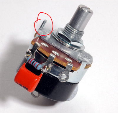
To fix them I had to fold the little piece of what you see on that picture :
120113032220420669294525.jpg


But by doing this I broke them  :-\... Do you think it can be an answer to my problem ?? Or my question's stupid ? :)
 
You can slightly drill the front panel at this place.  ;)

acoustix said:
Hi DIYers
I received my order from mouser and I have a question about capa.

For 100uF, 1uF and 47uF I took the Panasonic recommends that Mike's BOM, but I also took Nichicon muse ES Bipolar
Here the technical spec http://www.hificollective.co.uk/pdf/nich_es.pdf

My question is: Can I use these capacitors?
The fact that it is not polarized troubles me. (and it still have one leg longer than the other like polarized ??)

For 1uF, I think I can use them because they are linking capacitors (on the RevA, they are FILM ...), but for others, I do not know ...

Thank you!

Any ideas ?
 
Just a quick question for anyone who's done or knows the build....

I have  two 6.8uF caps,one which is a Tantalum.

There are two 6.8uF cap traces on the board, C19 and C17.Which one of these is the Tantalum?

Also why do the 1uF traces have 4 holes instead of just 2?

Thanks
 
...erm,Forget that!!

I think I've just answered my own question...just noticed C23 is in power supply section so presumably wouldn't be a Tantalum.
 
Yes,it's me again with what is yet another probably tedious and annoying query!

I was just wondering about the traces for the Trimmer Resistors on the board....I was wondering if all 3 holes are on the same trace/path on the board as they are quite close together and was wondering if it mattered if the solder joined them on the back because I'm out of small diameter solder and might find it tricky without it?

From what I can see of the traces it doesn't look as if it does.The schematic also doesn't seem to indicate that this would matter.


Also amongst all the ref material I couldn't find the value for the resistor on the release pot (probably me being dumb!) so I went with what I saw in MNAT's pic which I read to be a 270k.Is this correct?

Thanks in advance.


Back
Top