You are using an out of date browser. It may not display this or other websites correctly.
You should upgrade or use an alternative browser.
You should upgrade or use an alternative browser.
[BUILD] 1176LN Rev D DIY
- Thread starter mnats
- Start date


Help Support GroupDIY Audio Forum:
This site may earn a commission from merchant affiliate
links, including eBay, Amazon, and others.

Majestic12
Well-known member
What do you wanna have for it ?
did you remember to put the jumper at R44 back INTO circuit after doing step 2 of calibration?
sr1200 said:did you remember to put the jumper at R44 back INTO circuit after doing step 2 of calibration?
Yes... And I did the calibration x20 times... :-\
I dont know what I can check now...
I'm desperate now :-X
aaaAAAAHHHHH !! j'vais faire une p'tite pauseanjing said:Du calme Germoju, après tout ces efforts lâche pas!
")
Majestic12
Well-known member
Only one small question. When applying the 1khz tone for calibrating, should I feed the signal to Pin 2 and Pin 1 + 3 ? That's the right way of feeding a unbalanced signal to a balanced input, isn't it ?


![Soldering Iron Kit, 120W LED Digital Advanced Solder Iron Soldering Gun kit, 110V Welding Tools, Smart Temperature Control [356℉-932℉], Extra 5pcs Tips, Auto Sleep, Temp Calibration, Orange](https://m.media-amazon.com/images/I/51sFKu9SdeL._SL500_.jpg)


TheWolfman
Well-known member
- Joined
- Nov 1, 2011
- Messages
- 69
Hi,
I've just begun the construction of my Rev D and have just got around to mounting the Input and Output Pots.Upon getting to this particular stage I have noticed that the pots I have received in respect of the BOM from Mouser aren't suitable for two reasons:
a)I only actually received one of them!
b)As the controls pass audio I would like to use a better quality pot.
Thus I was wondering if any of you equally nutty D.I.Y'ers had any recommendations for a suitable replacement pot which isn't going to cost the earth?
Thanks
TheWolfman
Well-known member
- Joined
- Nov 1, 2011
- Messages
- 69
....also any recommendations for pot's with the correct bushing size would be kinda nice.
Echo North
Well-known member
TheWolfman said:Hi,
I've just begun the construction of my Rev D and have just got around to mounting the Input and Output Pots.Upon getting to this particular stage I have noticed that the pots I have received in respect of the BOM from Mouser aren't suitable for two reasons:
a)I only actually received one of them!
b)As the controls pass audio I would like to use a better quality pot.
Thus I was wondering if any of you equally nutty D.I.Y'ers had any recommendations for a suitable replacement pot which isn't going to cost the earth?
Thanks
a) The input attenuator is a custom part and is in the Hairball kit
b) The $7 bourns pot listed in the Hairball BOM as an "upgrade" is a good pot. Though some here will tell you they like the alapa that is in the mouser cart
c) Frontpanel bushing size is 3/8" or smaller.
I made this list for me maybe can help someone...
A - SIGNAL PREAMP
R4 270R
R7 2,2M
R5 27K
R6 2,2M
R10 10K
R8 1K
R18 180
R13 1M
R84 180
R85 150
R11 82
R14 22K
R12 1,8K
R9 560K
R15 6,8 K
R17 6,8K
B - SIGNAL LINE AMP
R25 2,7M
R24 2,7M
R27 1,5K
R28 27K
R3110K
R26 68K
R34 8,2K
R33 560
R29 1,2M
R30 150K
R3239
C - GR METER DRIVER
R72 1,5K
R66 10K
R65 3.9M
R73 680
R70 4,7K
R79 15K
R68 1,5K
R67 3.9K
R74 2,7M
R69 1,5K
R76 8,2K
D – GR CONTROL AMP
R64 1,5K
R35 10K
R60 3.9K
R37 470K
R36 1M
R46 47K
R38 47K
R39 4.7K
R53 47K
R40 2.4K
R41 270
R42 182K
R43 38.3K
R48 7.68K
R51 4,7K
R47 44.2K
R52 47K
R49 2.7K
R50 180
E – POWER SUPPLY
R87 1.1K
R89 220
R82 1K
R81 1K
TheWolfman
Well-known member
- Joined
- Nov 1, 2011
- Messages
- 69
Thanks for getting back to me Mr Echo North,
Yer sorry my post was a little confusing,I meant I was missing the release Pot from my Mouser BOM.Yes I have the input attenuator.I would just like to replace the output pot with something a little better than an ALPS and also one which has the correct 3/8 shaft size as I dont like fitting pots into a wrong sized bushing as it feels a little cheap.Same goes for the Attack and Release Pots,would like a pot with the correct 3/8 size.
Any recommendations on this?
Echo North
Well-known member
TheWolfman said:Thanks for getting back to me Mr Echo North,
Yer sorry my post was a little confusing,I meant I was missing the release Pot from my Mouser BOM.Yes I have the input attenuator.I would just like to replace the output pot with something a little better than an ALPS and also one which has the correct 3/8 shaft size as I dont like fitting pots into a wrong sized bushing as it feels a little cheap.Same goes for the Attack and Release Pots,would like a pot with the correct 3/8 size.
Any recommendations on this?
The bourns output pot has a 3/8" bushing. The output and release are tough. Keep in mind they are not in signal chain. You need a 5M and a 25K with a switch. Not easy to find off the self. The only ones I have found are the alpha's in the BOM.
gemini86
Well-known member
Echo North said:TheWolfman said:Thanks for getting back to me Mr Echo North,
Yer sorry my post was a little confusing,I meant I was missing the release Pot from my Mouser BOM.Yes I have the input attenuator.I would just like to replace the output pot with something a little better than an ALPS and also one which has the correct 3/8 shaft size as I dont like fitting pots into a wrong sized bushing as it feels a little cheap.Same goes for the Attack and Release Pots,would like a pot with the correct 3/8 size.
Any recommendations on this?
I think you meant attack and release, echo.
The bourns output pot has a 3/8" bushing. The output and release are tough. Keep in mind they are not in signal chain. You need a 5M and a 25K with a switch. Not easy to find off the self. The only ones I have found are the alpha's in the BOM.
Echo North
Well-known member
Ahhhh yes sir. Thank you.
Attack and Release.
These threads are full of me confusing the **** out of people
Attack and Release.
These threads are full of me confusing the **** out of people
TheWolfman
Well-known member
- Joined
- Nov 1, 2011
- Messages
- 69
Ha ha @echo...no worries!
....and thus the stumbling continues:
I got the Avel Linberg (or Avril Livine as I like to call it!) with the kit,but im slightly confused by the wiring configuration on it.The wiring diagram on the actual transformer look's like this:
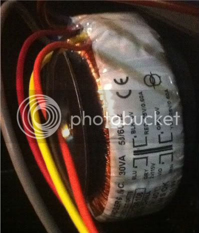
This indicates that the hot outputs are the Red and Yellow and the Cold 0v are the Black and Orange.This configuration however does not comply with the standard on the Avel Lindberg site which MNATS links to:
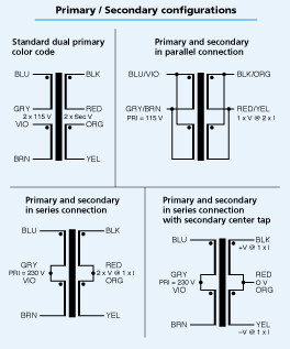
In this configuration it looks like the Red and Orange outputs are the Hot and the Black and Yellow are Cold.
Now im totally confused with which configuration to go with,particularly now for the input of the transformer.
Any help would be much appreciated.
Thanks in advance from a baffled DIY'er!
....and thus the stumbling continues:
I got the Avel Linberg (or Avril Livine as I like to call it!) with the kit,but im slightly confused by the wiring configuration on it.The wiring diagram on the actual transformer look's like this:
This indicates that the hot outputs are the Red and Yellow and the Cold 0v are the Black and Orange.This configuration however does not comply with the standard on the Avel Lindberg site which MNATS links to:
In this configuration it looks like the Red and Orange outputs are the Hot and the Black and Yellow are Cold.
Now im totally confused with which configuration to go with,particularly now for the input of the transformer.
Any help would be much appreciated.
Thanks in advance from a baffled DIY'er!
gemini86
Well-known member
It doesn't matter so long as you pick one or the other. Don't cross phase on the input or output and it'll function the same no matter what you call hot or cold.
Echo North
Well-known member
The dot indicates the polarity of the winding. The "25V/0.6A" is referring to that windings capabilities as a whole. If that makes sense.
For this build your creating a center tap to ground (red and orange) and Black and Yellow give you your two 25V/06A leads (both positive). I would pay more attention to where the black dots are placed rather than the "25V/0.6A" or "115V". They seem a little misleading here.
For this build your creating a center tap to ground (red and orange) and Black and Yellow give you your two 25V/06A leads (both positive). I would pay more attention to where the black dots are placed rather than the "25V/0.6A" or "115V". They seem a little misleading here.
Echo North
Well-known member
gemini86 said:It doesn't matter so long as you pick one or the other. Don't cross phase on the input or output and it'll function the same no matter what you call hot or cold.
What he said
TheWolfman
Well-known member
- Joined
- Nov 1, 2011
- Messages
- 69
Thanks for the swift reply Gemini86.
So if I follow you right,what's important is that is that I use the connections which are parallel with the respective windings.
I have chosen Red and Yellow for the + outputs as indicated on the diagram on the actual transformer itself.So if I've understood you right I should choose Grey and Brown for the + on the input?
Oh yeah,I forgot to mention that im in London UK,so I need to wire the input for +240v.
Similar threads
- Replies
- 5
- Views
- 576
- Replies
- 2
- Views
- 558