[BUILD] 1176LN Rev D DIY

GroupDIY Audio Forum

Help Support GroupDIY Audio Forum:

This site may earn a commission from merchant affiliate links, including eBay, Amazon, and others.
Then the grounding point was the issue.  I measured again, ground both test points to the Center Tap and I get +29.75
-9.87!  Thanks for the timely and informative responses. 
 
I just noticed someone selling a rev D on ebay with an mnats board. I'm just wondering how serious the disclaimers are. Could mnats sue over this? Is it against the law in the US, Australia or International? How are Purple and Mohog allowed to sell clones? Is Urei's patent expired?

If I did a poor job on the build could I sell it to some schmuck?  ;D Or if I didn't finish it could I sell the parts legally so I don't have $500 of worthless, to me, junk? Just want to know what I'm doing before getting too involved.

 
Personally, out of respect for MNATS (and i belive all praise and respect is due to him), i wouldn't put a unit up on ebay completed. If youre having trouble with the build follow mnats site to a tee, if you still have questions, ask, id be glad to help, and would even skype some troubleshooting. If you feel its totally a lost cause, i would offer the board/parts on here first to kind of "keep it in the family". Barring a horrible soldering job where pads are destroyed, there shouldnt be any catastrophic failures if you follow the directions. Theres SOOO much to read on this project, i know it can be a bit overwhelming, but stick to the trusted sources of info (mnats site for wiring, hairball site for the switch implementation, if building that version) and youll be fine.  If you have no experience soldering or following a schematic, get yourself some perfboard and a bargain bin sack of components and just practice soldering, then get some of those $20 kits the have at radio shack and practice something that works and that you can follow the diahrams and scematics.  Youll learn a lot of skills that will make your BIG projects (like this one) successful, and if youre too afraid of failure, im sure you could hire someone to build one for you, or just go to UA or purple and go for a unit that has a warranty.
 
  Does the orientation of the trim section of the trim pots make a difference? I understand that the orientation of the entire pot needs to be at a 90 degree angle as shown off the hairball site, but I'm wondering how the user serviceable brass section needs to fit in.

  Thanks for the help,

  -P
 
I pondered the same question last night, as I was stuffing the PCB.  As the amateur that I am, I assumed that these trimmers are merely variable resistors and are therefore not assigned a polarity.  Current moves through a resistor regardless of it's orientation and a trimmer is like having a little monkey swapping out resistor values to correspond with the degree of the trim knob rotation.  I look forward to hearing if my "picture pages with Bill Cosby" understanding is near accurate.
 
the trimmers can be mounted either way,  only difference is the direction you'll need to order the monkeys turn the screw to increase or decrease the resistance.

btw the "good for searching within topics" box in the upper right corner is your friend in these large support threads, many people run into the same issues during their builds.
 
My dual Rev D (rotary) is so close to being fully operational. After battling miswired output transformers and broken Lorlin pins (don't know how that happened)... I seem to be fully operational except that my VU setting on channel 1 will not work. The +/- on the meter outs are showing continuity, which they shouldn't. On the GR setting, there is no continuity, which means it is not simply that the meter itself or meter wiring is shorted.

I'm using the rev 1 main, ratio and meter boards. I can't find layout docs for the original meter and ratio boards. It would be helpful to know what the switch is supposed to be doing at least. It seems that, on the VU setting, it should be a straight path from X + Y to the meter (with the 3.6k resistor in series with Y). This is almost the case, but there is some kind of shorting going on.

If anyone knows where those docs are available it would be helpful.

Thx

Tim


If the AC side of the transformer cuts off and -10V goes away (but +30V is still there, although somewhat closer to +34V), will it hurt transistors in the sidechain section? I have some very weird behaviour after my -10V dropped off...
 
timmygrimm said:
I can't find layout docs for the original meter and ratio boards. It would be helpful to know what the switch is supposed to be doing at least.

The rotary meter and ratio boards provided with the Rev D are almost the same as the G1176-type layout posted on my site. You can see what the switch(es) are supposed to be doing by looking at the schematics.
 
sr1200 said:
Personally, out of respect for MNATS (and i belive all praise and respect is due to him), i wouldn't put a unit up on ebay completed. If youre having trouble with the build follow mnats site to a tee, if you still have questions, ask, id be glad to help, and would even skype some troubleshooting. If you feel its totally a lost cause, i would offer the board/parts on here first to kind of "keep it in the family". Barring a horrible soldering job where pads are destroyed, there shouldnt be any catastrophic failures if you follow the directions. Theres SOOO much to read on this project, i know it can be a bit overwhelming, but stick to the trusted sources of info (mnats site for wiring, hairball site for the switch implementation, if building that version) and youll be fine.  If you have no experience soldering or following a schematic, get yourself some perfboard and a bargain bin sack of components and just practice soldering, then get some of those $20 kits the have at radio shack and practice something that works and that you can follow the diahrams and scematics.  Youll learn a lot of skills that will make your BIG projects (like this one) successful, and if youre too afraid of failure, im sure you could hire someone to build one for you, or just go to UA or purple and go for a unit that has a warranty.

Thanks SR1200. I'm going to figure out how to build one of these and hopefully not botch and have to start over again too many times.  But I'm also curious about the rules/laws/"respect". Is the "not for commercial use" disclaimer more about patent issues with Urei or UA than it is with mnats or Hairball? I would think that mnats and hairball wouldn't care about downstream as long as people purchase their products and they're not responsible for anything. Maybe this is blasphemy(it is naive) but I see a little capitalist opportunity to make a profit through the labor of assembling one of these. If it costs $500 in parts then labor is likely worth a few hundred. I mean no disrespect to anyone. It's just an observation that I would like to know more about so that I know the rules in order to not cross boundaries unwittingly. 
 
Believe me I've thought about doing it, and I certainly would build a box if a member or fellow studio owner asked me to. Yes, I would have to charge for my time (which would still be less than buying a UA or Purple unit), but by no means would I do this on or near a commercial scale. 1 or 2 maybe if im bored lol.

When all is said and done, I would never take his boards slap my own name on it and put out for sale... Just goes against my conscience.  This guy (well, mnats and gyraf) took the time to create these boards, from what i understand has had at length discussions with the maker of the trafos that we use in the kits for them and has done the leg work for what i can surmise is not much profit per board (for what he's selling them for).

I personally dont believe that Purple should have reissued it, but im sure they went the legal route and covered their bases doing it; UA, obviously, has every right to.
 
  I'm putting together my t-pad pot, and I want to make sure that it's orientation is correct before I solder this in place. Is this right?
 

Attachments

  • t-pad.jpg
    t-pad.jpg
    258.2 KB
sr1200 said:
. 1 or 2 maybe if im bored lol.

that's what I was thinking. If I built some for other people then I could afford other DIY projects. But I don't want to be red-flagged and banished to hell. Now back to my pre-1176 experiment.
 
Nearing the end of my Rev D wiring and I have a question, regarding these instructions from the Meter Circuit and Output section of the MNATS wiring pages:

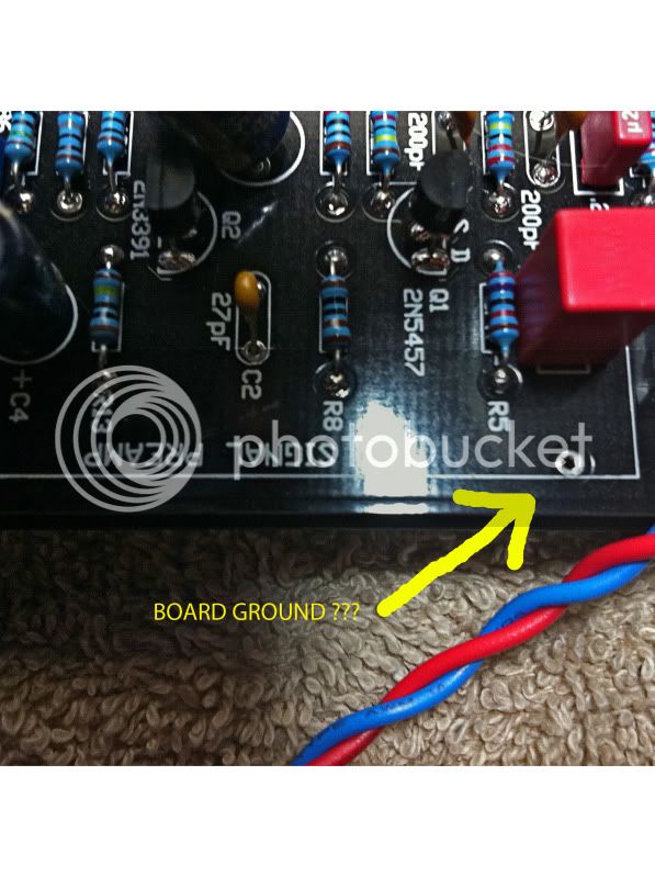
"Solder a heavy wire from the board ground nearest the large capacitor in the power supply. If your board does not have a pad here simply solder the wire to the negative pad of the large power supply capacitor C25."

I'm was planning to use 16 guage wire, as I did with the IEC ground.  How is it that you are able to squeeze the girth of the 16 guage wire and the negative lead of C25 through the same PCB hole to solder?

OR...in the picture I have attached, is that a board ground that could substitute for wiring to (-) of C25....?.?.?...

boardground.jpg
 
I think the idea is just to solder the wire to the pad / trimmed lead of the cap on the bottom of the board, not to put the gnd wire through the hole. That's what I did anyway. It made a pretty sturdy connection (if that was a concern).
 
Hey guys.  Does anyone have a list of voltages I should be reading at tl071 and tl072 from the stereo link boards?  I am getting proper 30vdc to the 30v pad.  My 2 rev D's work perfectly in mono but when I flip the switch to stereo I get no gain reduction.  The meters do not show any reduction and there is no "actual" gain reduction.  In stereo mode i still get sound from both units just no reduction.  I wired it up exactly as on the hairball diagram, with the exception of mounting my switch in an exernal enclosure.  I used a dpdt instead of 2 spdt's and connected a TRS cable from each mono comp to the external enclosure. I also jumped the 2 comps together with a TRS cable as proposed in the diagram. Other than the voltages if anyone has any ideas please chime in, thanks...
 
  I'm confused about my values for the two pots that I have left. I have a 250K and a 2K pot. The release pot on my bill of materials is marked as a 5M. Did I get a wrong part? Also, is the 2K for final output?

  Thanks for the help,

  -P
 
As per the MNATS BOM on his site...

The 2k is your 0 adjust
25K is Attack (or get the one from hairball)
5M is Release
The 600 Ohm "T-pad" is your input
250K (Audio)...... (theres only one left...)
 
Back
Top