[BUILD] 1176LN Rev D DIY

GroupDIY Audio Forum

Help Support GroupDIY Audio Forum:

This site may earn a commission from merchant affiliate links, including eBay, Amazon, and others.
I have a unbalanced valve preamp that I like to use to dirty things up a bit. Problem is, by the time it's had a chance to dirty, the output level is crazy hot. I've been chaining through the 1176 with the input knob way down which works a treat sound wise but how careful do I need to be to not damage the input tranny?The input attenuator comes before the input tranny so I would expect this to be ok but I'm no expert.

Also, I have some unbalanced synths and distortion pedals etc that I'd like to treat audio with but a lot of the time they will eventually need be connected to the balanced input of the pultec or the 1176 etc. Set up in the patch bay, I've been connecting to the balanced input with an unbalanced cable which means 'hot' is connected and 'cold' is grounded as well as shield. This also results in half the level so I'm needing to pump a lot more into the 'hot' side to see a decent level on the eg. 1176. Regardless of noise, is this 'ok' or am I going to hurt the input tranny's on my gear doing this?
 
Ahhh Q6,I didn't test because I was measuring from the front of the board and it's hard to probe it.I will measure today....

I have realised that Q12 and 13 need to be matched,which I didn't realise until now,I was wondering why Mouser sent me 20 of them!However this still wouldn't cause the readings to be so far out....or would it?

Any ideas....anyone?
 
Ive read up all the info on Mnats site about matching Q12 and Q13 as well as Q7 through Q10.

Ive never had much electronic experience before except a few classes in high school.

Ive also never measured transistors like these N3708 before.

Can someone PLEASE give me some information on how exactly to measure them?

Google doesnt give me results that can be applied to this situation.

Thank you kindly.
 
Slightly disappointed that no one can lend any advice from experience regarding my FET voltages I have to say....

@Ilove1176 Here are some good links regarding FET matching:

http://www.groupdiy.com/index.php?topic=4531&highlight=fet+matching

http://www.geofex.com/Article_Folders/fetmatch/fetmatch.htm

http://www.firstwatt.com/pdf/art_mos_test.pdf

I am going to breadboard a jig to test my FET's this afternoon if all goes to plan.I can post pics of my rig for you if that helps?
 
CHECK LIST:
Have you checked the polarity of all your caps?
Have you checked all your diodes and transistors for orientation?
Did you ever get that Q6 value? 
Did you make the correction for R12?

if you did have parts that were/are in the wrong way, you may have to replace some transistors.

As far as the matching goes, this only matters to match the meter to what the circuit is actually doing in the box.  Easiest way would be to buy the matched pair from Hairball. Id rather pay a few bucks extra for someone else to test and match than for me to have to build a test circuit and go through a bag full of them. lol but thats just me being lazy.

I can see from your pics that you made the same mistake I made on my second unit of putting the front panel meter adjust rheostat to the tracking adjust and not the 0 adjust (might wanna switch that around... but wouldnt cause your problem)

 
Thanks for getting back SR1200,much appreciated.

All Diodes,Caps and Transistors are correct orientation.

R12 correction?

Oh shhhhhhhhheeeeeeet,I have got the tracking adjust and 0 adjust the wrong way around!I never noticed that....OOooooops!Oh well no biggy but thanks for spotting that one!

Q1 and Q11 are matched..I got them from Hairball.I also thought it was important to match Q12 and Q13 though?
 
As indicated on the original schematic, some details regarding the transistors should be noted. Select Q12 and Q13, matching hFE within 10% (the absolute value is not critical). This will allow proper calibration of the meter driver circuit and correct operation once calibrated.
Matching within 10% isn't too hard especially when the actual VALUE is unimportant.
And yes 1/11 are the hairball ones its been a few months since my last build.

Revision D Version 2.2 26.01.09 (currently being supplied):

    R12 Value should be 1.8k rather than 920
 
I had the chance to a/b test my 1176 rev D against the real deal today. The UA unit was according to its serial number a rev D as well, if i understood it right.

I had some unprocessed tracks with electric bass and guitar and some vocals. The signal was split into two channels on a mixer and the 1176s inserted on one channel each. This made it easy and fast to switch between the two. I had one Genelec 1031 for monitoring.

The input and output knobs ended up in quite different positions to get the same amount of gain reduction/output, but after some dialing in my first impressions were really positive. They both sounded great and really brought the tracks alive. However, after playing around for a while i felt that the UA unit added a little more "bite" to the sound when mine was a little bit kinder. It was hard to admit but i liked the bite more.

Another thing i noticed when playing some bass tracks through the units was that my unit added a very subtle low cut to the track, has anyone else noticed this as well or should i start troubleshooting? I went with Katos BOM and the Hairball bundle when i built my unit and afterwards changed the input transformer to a UTC 0-12.


/Edward
 
I'm attempting to match my 2N3708's in the transistor tester in my multimeter.Upon inspecting the Datasheet for the Transistor it seems as if the ECB is labeled incorrectly on the data sheet as when inserted into the multimeter NPN test socket with the ECB orientation shown on the datasheet no hFE value is displayed:

http://www.centralsemi.com/PDFs/products/2n3707-3711.pdf

However when I reverse the transistor so that it is effectively behaving as a BCE Transistor it reads a value somewhere between 200-350.Is it possible that the Datasheet is incorrect?

 
  Ok, I'm about to put all of my transistors in. I'm wondering about the extra holes above some of the spaces. For example, what is the hole above Q12, Q8 and Q9 for? Also, in my order I received 3708 NPN transistors, the board is marked for 3707s.
 
@pitts - same thing
@ ed - mine are both stock hairball... i always my own bom, but if anything i notice mine actually accentuate the bottom end.  tranny difference perhaps.  there was a comparison i think in tape op a while back and their findings were very close to my own.
 
Thanks sr1200. Found the review i believe... http://tapeop.com/reviews/852/
Great review.

It is true that while the original UA was better on some sources the clone was superior on others. Both fantastic units.

Think i need to start troubleshooting... O-12 is the first suspect.


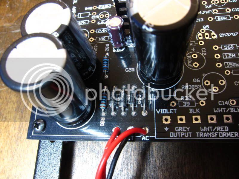
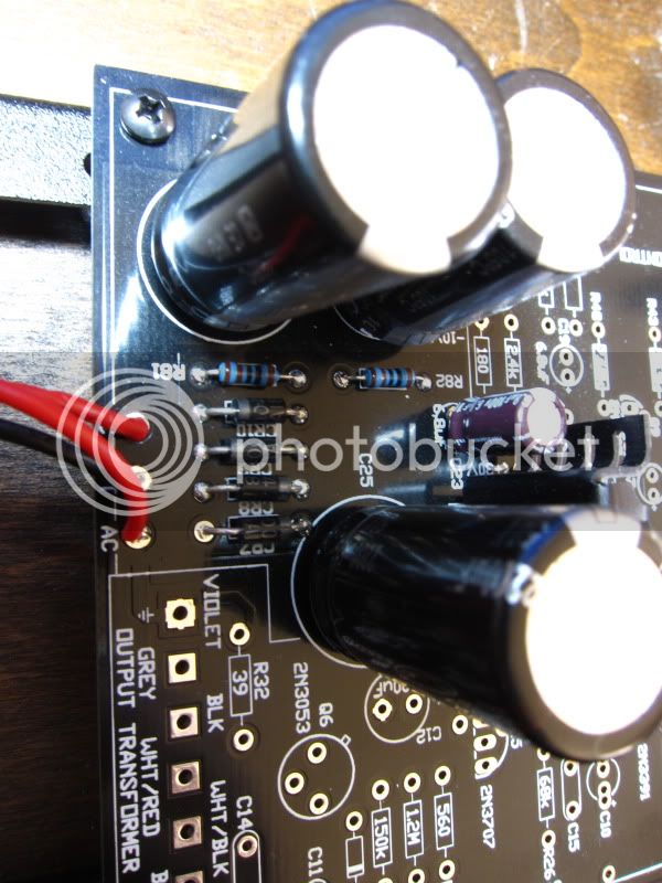
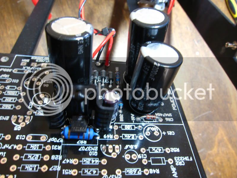
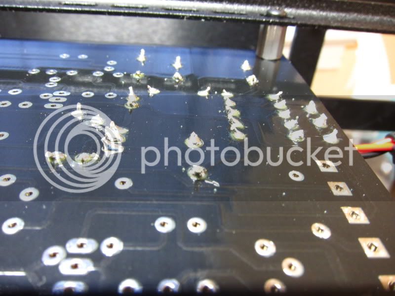
Hello all.  I've just begun my first Hairball/Mnats build.  I've wired up the power supply and began to test, after quadruple checking everything.  I'm seeing 30VAC at both "AC" points on the PSU section of the board, however my DC readings at the -10VDC and +30VDC test points are not registering anything.  All of my diodes and capacitors are oriented properly, unless I'm blinder than blind.  Is this most likely a soldering issue?  I was about to reflow all points, but I don't want to heat up the PCB unnecessarily.  Could somebody check out these photos and see if I'm overlooking something?

Also, is it necessary to run a ground wire from the PCB to chassis or does the board ground through the center tap wire on the transformer?

I really appreciate your time and the help!

IMG_1117.jpg

IMG_1116.jpg

IMG_1118.jpg

IMG_1119.jpg
 
The board gets grounded when you're wiring your output transformer in later on.  I dont think i've ever tried to check the voltage before the entire board is stuffed though...
 
That's right...I'm placing the (+) MM lead at +30 point of R87 and the (-) MM lead to the chassis.  Same for the -10 point of CR6.  The MM reads OVDC in both cases. 

SR1200...on Hairball's site, he recommends building and testing the PSU prior to stuffing the remainder of the board.  To protect all of the remaining board components from an incorrectly wired PSU (by amateurs such as myself) and to simplify troubleshooting.
 
i did the same (stuffed the psu area first as recommended) but measured between the test points and the center tap (0) on the board* - showed the correct voltages. your parts all look to be oriented correctly.

if sr1200's assertion is correct about the board grounding to chassis not occurring until output xfrmer wiring, this sounds like the issue with measuring w/ respect to the chassis at that point, i imagine

*i'm not an expert, be careful
 

Latest posts

Back
Top