[BUILD] 1176LN Rev D DIY

GroupDIY Audio Forum

Help Support GroupDIY Audio Forum:

This site may earn a commission from merchant affiliate links, including eBay, Amazon, and others.
Just like the problems I had, I see there are other people who have some trouble measuring the hFE of the 2N3707/8 transistors or finding information about the best way to do these measurements. I don't know if this is the best way (I hope it is at least correct), but since in the end it was rather easy, I would like to show what I have done.

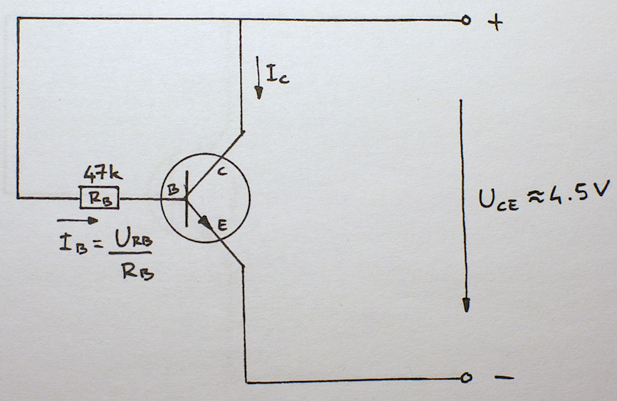
I also have a DMM that is supposed to be able to measure hFE. However, after trying all possible directions and pin combinations, the only measurement result that I could get was something around 1000. As we know from the specs the max. hFE for the 2N3708 is somewhere around 600, so that these results were obviously rubbish. I searched the interweb for some other measurement methods and in the end I came up with this setup:
DSC_3831.jpg


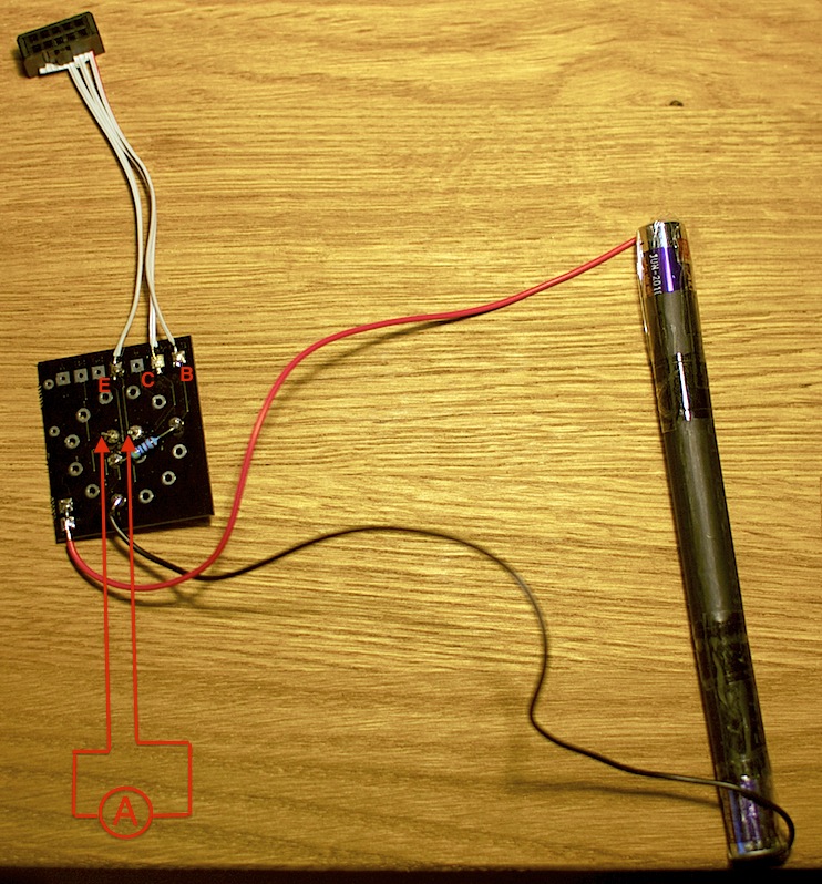
The little test rig is this (constructed with some scrap material):
DSC_3829.jpg


A DMM is attached to the two pins on the small pcb and set to mA. This will give me the collector current Ic.
The transistor to be measured is inserted in the appropriate holes of the 10 pin connector.
By measuring the voltage across the 47K base resistor, I know the base current Ib.
Finally: hFE = Ic/Ib

With this test rig I got reasonable hFE values around 290. I measured 10 transistors and they were all very close to each other.

I noticed that the measurement is very temperature-sensitive. Before writing down the mA value I waited 1 min for each transistor to heat up. After that time the value was much more stable.

My rev D 1176 is now finished. The voltages at the transistors were correct right away and the calibrations were a piece of cake. Now I'm doing some sound testing and so far it is great. Thanks Hairball Audio and Mako for the great kit!

Hope this helps someone else along the way to his 1176. Please correct me if I got something wrong.
Cheers, Mattia

 
sr1200 said:
Lets try this.
Go back and re-do the first two calibration steps.  (pay close attention to when/where the jumper is on / off)
Then, on step 3, after you 0 the meter, turn the input up to like 75-80% instead of 50% then see if there's a bigger drop.

It could be that your adjustment pot is turned all the way one way, in which case you might not see a drop. 
If the needle DOES infact move, (albeit a tiny bit) I dont think you're far off.

Thanks sr1200, I will take this advice on board and try it out... my build is actually a rev F, the only reason I chimmed in on this thread was because I noticed there were other members with exactly the same problem I had (because the calibration fundamentals are the same).

Even without the calibration, for some reason yet to be determined, it doesn't 'sound' like its compressing, even though the VU meter and all pots & ratio selections indicate GR on the VU meter...
 
I'm getting started with my Hairball/mnats rev. D 1176 and I'm wondering if my power transformer is healthy.  I've built the power supply section of the PCB and tested for the -10 V and +30 V and things were out of whack.  The PCB appears to be populated correctly: no incorrect parts or backwards caps/diodes.  I desoldered the transformer from the board and tested some voltages there.  With the DMM set to AC volts and the black probe on the ground lug of the AC plug, I'm seeing 122 V at my live wire as I would expect.  I'm seeing 10.4 V on the black secondary, 39.2 V on the yellow secondary, and 14.3 V on the center tap.  I expected to see 25 V on the black and yellow wire and 0 V on the center tap pair.  Is my transformer behaving strangely?  I separated the red and orange wires and tested for continuity to see if a wire may have been mislabeled at the factory.  I ring continuity between black and red and between orange and yellow as I expected.  What's going on here?  My transformer is the Avel Lindberg Y236106 and it was wired according to mnats Avel-Lindberg specific instructions.  The markings on my transformer conform to other photos I've seen in this thread.  I can provide photos if they will help.  I know enough about this stuff to be dangerous!
 
What if you measure the transformer secondaries with the black probe of the DMM on the CT? If we take your 10V measurement on the black secondary as negative, you have approximately -10, 15, 40, which would be 25V difference from the CT. Don't know if it makes sense, but the transformer might be fine.

However, that still leaves you with your problems in the power supply section. What voltages do you measure instead of -10 and 30? Stupid question, but did you set the DMM to DC V? Where do you put the black probe (should be on the CT or somewhere else with the same potential)?

Mattia
 
let's try this again.

Trying o figure out the issue with the attack time.
I'm measuring the section around the attack pot.

So, the 2 tantalums will see 14v and 16v ish on the + side. If 21 and 19 are removed (21 - connection to ratio board, 19 connection to attack pot) the circuit will be open and since the capacitors are blocking DC that should be the end of it. 0v on the negative side, through the diodes, all the way to the pad.

Now, I'm measuring -7v (same as R64, unit compression OFF, 20:1 ratio, fast release). I can't see any short so is there anything else that could cause this problem?

My unit is not behaving as it should, compared to original 1176 and some older mnats  revD that I got hands on.
 
I'm all good now!  Thanks for the replies.  Once I was referencing the black probe to the CT, all my voltage readings came up normal.  On to stuffing the rest of the board...
 
well finally completed my kit and alas something is wrong, i think that i have 2 main issues.

first, a grounding issue because it passes audio but the signal returning back into pro tools is one decreased in volume and has a ton of noise, i tested the input circuit and it was clean as a whistle, so i can check that off, but my output pot does something weird at negative infinity its is can be loud, turn it up 50% and it gets quite, then 100% loud again, also it increases noise around 75%, the wiring looks right to me, and i think the noise at 75% is just a scratchy pot needing cleaning. once you get past 75 its gets cleaner (but still a ground issue so still noisey) but this is one i will hunt down peice by peice and wire by wire. i have an wired suspicion its actually my case.... thinking removing the powder coat at the screw holes would be a good step? to make a better connection like the input transformer 


second, i am not getting compression or my meter is not responding to it..... it passes audio but its noisey and does not sound compressed... i zeroed the meter with no signal and tried to do the first calibration step, but when putting it on +4 and 20:1, with a 1khz signal at 0db, the meter pegs down and turning the q bias does nothing at all.... the trimmers are linear correct and their orientation does not matter?

also it seems everytime i move the unit i have to re-zereo the unit, im using a trimmer on the pcb because for the life of me could not  figure out how to install the 2k pot on the front panel, am i compromising quality by doing that?


will take pics and make a video soon to see if yall can help me with my build... i hate when builds go dont work  :-[ but i would never learn anything if they didnt. 


ohh and just wondering but my output transformer wires  are insanely short, there is a lot of tension on them, if i had mounted it at near the power transformer it wouldnt have reached the xlr and mounting it near the xlr puts great strain on some of the wires to the pcb, was anone else's like this?


again ill try and post pictures and a video with what is going on with my unit as soon as possible, class is kicking my arse right now so it might be a few days.

thanks in advance because i know how supportive and help all of you are. i have tried to read through the thread to find my answers but at 176 pages its easy to read over things. reading over the no compression but audio issue post on the last page, will the correct voltages for the fets change due to it being a rev a? after hunting down this ground issue i will start testing the ratio and meter driver stage.


okay this is getting insanely long, must be because im procrastinating while pulling an all nighter... sorry for that.


yep i see a wiring issue already, where does pin A connect to on the ratio board, i looks like the wiring diagram i had let of a few bits
 
Few things.

I'd start by disabling GR (confirm pad 22 is shorted to ground).  No you basically have a two stage mic pre with about 40dB of gain.  Let's get that working and passing a signal.  Then move to the GR portion.

Look at the schem and focus on the top two blocks:
http://mnats.net/files/1176REVD_VOLTS.pdf

Check you voltages.

The CW lug of the output pot should go to pad 15. See here:

http://mnats.net/1176_reva-d_hairball_wiring_output_zero_pots.html

Mike
 
I posted those last too a little too fast, I ment the attack knob not the output. So pin A from the attack to GRN on the ration board? My pin A isn't going anywhere.


Ill do the gr short tonight as well as check voltages again. For the pad 22 short could I just take it out of the molex and insert it in with the ground next to it? Would that work?
 
If you get stuck, mnats guide on his site has pictures of just about every step of wiring.  I even went so far as to use the same colors as his for my first build.  Follow along with that step by step, you almost cant go wrong.  Keep in mind too there are a couple of instances where a shield is connected on one end and nothing on the other.
 
berkleystudios said:
I posted those last too a little too fast, I ment the attack knob not the output. So pin A from the attack to GRN on the ration board? My pin A isn't going anywhere.


Ill do the gr short tonight as well as check voltages again. For the pad 22 short could I just take it out of the molex and insert it in with the ground next to it? Would that work?

No.

Do it on the attack switch. I you don't have an attack switch uses a jumper between pad 22 and ground.

If you have a Hairball kit.  Do as Sr1200 suggested and start by going through the step by step MNATS guide again. 

Thanks!

Mike
 
i have rewired the entire thing and i have Compression!!!!!!!  but my meter is doing something like an ssl the GR is backwards. at first i though my meter was just not working but i see gain reduction going up wards not down haha
 

Latest posts

Back
Top