[BUILD] 1176LN Rev D DIY

GroupDIY Audio Forum

Help Support GroupDIY Audio Forum:

This site may earn a commission from merchant affiliate links, including eBay, Amazon, and others.
I doubt it.  The meter board is very basic.  Either it works or it doesn't.  In GR mode it's not in the audio circuit.

Are you getting clean signal and GR in +4/+8?  Everything is working other than GR metering?

If so look at your meter driver section.  Were you able to do the null adjust and tracking?
 
Echo North said:
I doubt it.  The meter board is very basic.  Either it works or it doesn't.  In GR mode it's not in the audio circuit.

Are you getting clean signal and GR in +4/+8?  Everything is working other than GR metering?

If so look at your meter driver section.  Were you able to do the null adjust and tracking?

i am getting a clean signal and gain reduction in +4/+8, however the only noticeable gain reduction heard is all buttons in.

like i have said previously gain reduction is being read like an ssl meter... when heavy gain reduction occurs the needle moves right instead of left, other than that there is no movement in the needle it just pegs hard right no matter the ratio. ill try and take a video of what is going on this weekend at the studio
 
berkleystudios said:
Echo North said:
I doubt it.  The meter board is very basic.  Either it works or it doesn't.  In GR mode it's not in the audio circuit.

Are you getting clean signal and GR in +4/+8?  Everything is working other than GR metering?

If so look at your meter driver section.  Were you able to do the null adjust and tracking?

i am getting a clean signal and gain reduction in +4/+8, however the only noticeable gain reduction heard is all buttons in.

like i have said previously gain reduction is being read like an ssl meter... when heavy gain reduction occurs the needle moves right instead of left, other than that there is no movement in the needle it just pegs hard right no matter the ratio. ill try and take a video of what is going on this weekend at the studio

Sounds like there's more going on then.  A video won't help me.  You need to check your sidechain voltages.  Look back at my previous post on that recently.  The Pad 21/22 stuff.

You were able to calibrate the qbias correct? 
 
Read the 2-3 pages of this Steve_H exchange. Check the pad 22/21 stuff.

http://www.groupdiy.com/index.php?topic=29981.msg614820#msg614820

Start there.  You need AC @ pad 22 and -DC @ 21 as a starting point.

Make sure you are fully calibrated and check the voltages on the MNATS rev D page "typical voltages guide".

Report back with what is off.
 
jplebre said:
In fact capacitors you would most likely see it.

by that I meant they would either have leaked, opened the "vents" at the top, gotten bigger or exploded :p
but yeah you can test them with a DMM to make sure
 
Hey guys,

I have a question... I am trying to build a Hairball 1176 compressor and I'm using the Avel Lindberg transformer. Now the voltages seem to be off. I am in Europe, so 220V. But the problem is that the secondary windings give off about 130 V. I used the exact wiring from the Mnats site. Anybody knows what is wrong? Is my transformer broken? Thanks!
 
Chryst said:
Hey guys,

I have a question... I am trying to build a Hairball 1176 compressor and I'm using the Avel Lindberg transformer. Now the voltages seem to be off. I am in Europe, so 220V. But the problem is that the secondary windings give off about 130 V. I used the exact wiring from the Mnats site. Anybody knows what is wrong? Is my transformer broken? Thanks!

Primaries in series and sec center tapped.

Look at the middle two diagrams on the second row:
http://web.archive.org/web/20090914070140/http://www.diyfactory.com/data/transformer_connections.gif

Personally I would measure my secondary under load (attached to a PCB with only the power supply section stuffed)


Mike
 
berkleystudios said:
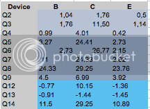
here are the voltages that I got

http://imgur.com/VXRaH72


Q8 is actually
14.70
30.00
14.23

Are any of them off by more than 10% (sorry I don't have the time to compare against the schem w/ voltages)?
http://mnats.net/files/1176REVD_VOLTS.pdf

Also check feed a 0dB signal into the input and set the output for 0dB.  Then test the AC at pad 22 under each ratio setting, then the DC at pad 21 at each ratio.  ALso check the DC at pad 18.

Mike
 
Jplebre and Mike,

Thanks again so much for y'all's help and advice!!

After checking all of the values I could (the caps checked out too), I decided to test as advised by Jplebre (Thanks!!) with my last fuse before my next order from Mouser came in to verify my suspicions about the linear regulator.  Well, no blown fuse and + 29.63 Vdc at the +30 Vdc and -9.78 Vdc at the -10 Vdc points!!  ;D I also observed +30.08 Vac at both the secondary windings.

It must have been user error on my part for the previous blown fuses.  Maybe using the AC voltage setting on my DMM to check the DC voltage points?

Either way I believe that it's safe for me to populate the board.

I believe +29.63 and -9.78 are in range... Do you think that these voltages will work from this point on?

Thanks!!
 
That's in range! Gluck

measuring dc with ac setting or vice versa won't affect it. Most multimeters will blow internal fuses (or get damaged) when measuring current instead of voltage or vice versa without changing the leads to the right sockets.

 
Awesome!!  ;D

Thanks for verifying those values for me, Jplebre!!

Ahh, okay.  That makes makes sense. Hmm... I wonder what I was doing to cause the blown fuses then?  Maybe the grounded locations I used when testing the power rails?  Who knows.  It doesn't seem to be a problem now.

Thanks again!!  I'm going to go build. :)
 
I have build a Hairball 1176 Rev D. Everything seems fine until the 3rd calibration step. The unit does not seem to compress. I have tried to look up my problem in earlier threads, but I can't seem to work it out. The voltages from Q4 onward seem to be off according to 

http://www.axtsystems.com/index.php?option=com_content&view=article&id=57:1176lnproblems&catid=34:1176ln&Itemid=62

Could it be a faulty FET? The screenshot includes my FET voltages. Any help is greatly appreciated. Thank you!

Schermafbeelding2013-04-30om205822_zpsc54201af.png
 
Chryst, Q4 looks good to me if you reference it against MNATS schematic.
Q4 is the first transistor of the o/p stage. Voltages are (CBE) 4.2v, 1v, 0.4v (aprox.)

If you have no compression, chances are your issue is in the GR section. Check your wiring as well.

That website is based on Rev J. Not sure what the differences are
 
Thanks Jplebre for your help. I've checked and rechecked the wiring. All components were checked before soldering and I've resoldered suspicious parts. Any suggestions are very welcome...
 
compare voltages against http://mnats.net/files/1176REVD_VOLTS.pdf

is it just compression you are not getting?

Follow the steps on this pages
http://mnats.net/1176_reva-d_hairball_wiring_attack_release.html
 
Hi!
I´m doing some DIY-Tetris today: planing to build a Dual-1776 for a friend and maybe a more experienced builder can give me a "go" on my case-layout?
The power switch will be at the right side, i´m planning to mount the input-transformers to the leftside-panel.
Will this layout do it (hum-free)? Or do you have any suggestions/ better ways to fill a case with all that boards and transformers?
Thanks!
Chris
Dual1176_Layout.jpg

 
So I finished the power supply on my Rev D unit and wanted to test it before moving on. I reflowed solder on all joints, and double checked that the fuse is good. I was curious what AC voltage was coming onto the main PCB from the transformer, so I used my DMM in AC mode (obviously) to test the AC1 and AC2 connections. I didn't notice what the readings were because a tiny puff of smoke came up from near the meter switch where the mains wires are connected. Naturally I stopped immediately and now I am posting here. My observations are that I forgot to use my ground probe for this test, and I think the only thing "damaged" by the smoke was the leads on the wires coming from the IEC at the switch. Where to begin? I just don't want to ruin any components (tranny!)

I should have prefaced this by mentioning that my DC voltages were off before disconnecting and reflowing solder joints, thus the reason for that. But at least there was no smoke!
 
cant tell if my DMM is just cheap and sucks or if my resistances are realy off... im thinking the later. a about three resisters in my GR Meter Driver section are off and this is the section where my tranistors are very off so im guessing that is the issue, just put a big order in from mouser to make sure i dont have any more faulty resistors.

will report back when they come in with the the results of the swaps
 

Latest posts

Back
Top