[BUILD] 1176LN Rev D DIY

GroupDIY Audio Forum

Help Support GroupDIY Audio Forum:

This site may earn a commission from merchant affiliate links, including eBay, Amazon, and others.
berkleystudios said:
cant tell if my DMM is just cheap and sucks or if my resistances are realy off... im thinking the later. a about three resisters in my GR Meter Driver section are off and this is the section where my tranistors are very off so im guessing that is the issue, just put a big order in from mouser to make sure i dont have any more faulty resistors.

will report back when they come in with the the results of the swaps

Remember R don't always measure accurately in circuit because or R's in parallel.  You need to de-solder and lift one leg to check the resistance.
 
tronnyjenkins said:
So I finished the power supply on my Rev D unit and wanted to test it before moving on. I reflowed solder on all joints, and double checked that the fuse is good. I was curious what AC voltage was coming onto the main PCB from the transformer, so I used my DMM in AC mode (obviously) to test the AC1 and AC2 connections. I didn't notice what the readings were because a tiny puff of smoke came up from near the meter switch where the mains wires are connected. Naturally I stopped immediately and now I am posting here. My observations are that I forgot to use my ground probe for this test, and I think the only thing "damaged" by the smoke was the leads on the wires coming from the IEC at the switch. Where to begin? I just don't want to ruin any components (tranny!)

I should have prefaced this by mentioning that my DC voltages were off before disconnecting and reflowing solder joints, thus the reason for that. But at least there was no smoke!

Hmmm proceed with caution.  Are you following the MNATS wiring guide and are you confident your transformer primary and secondary connection are correct?
 
Echo North said:
tronnyjenkins said:
So I finished the power supply on my Rev D unit and wanted to test it before moving on. I reflowed solder on all joints, and double checked that the fuse is good. I was curious what AC voltage was coming onto the main PCB from the transformer, so I used my DMM in AC mode (obviously) to test the AC1 and AC2 connections. I didn't notice what the readings were because a tiny puff of smoke came up from near the meter switch where the mains wires are connected. Naturally I stopped immediately and now I am posting here. My observations are that I forgot to use my ground probe for this test, and I think the only thing "damaged" by the smoke was the leads on the wires coming from the IEC at the switch. Where to begin? I just don't want to ruin any components (tranny!)

I should have prefaced this by mentioning that my DC voltages were off before disconnecting and reflowing solder joints, thus the reason for that. But at least there was no smoke!

Hmmm proceed with caution.  Are you following the MNATS wiring guide and are you confident your transformer primary and secondary connection are correct?
I am following the MNATS guide indeed, specifically for the Lindberg transformer. I've double and triple checked, but I will check yet again when I get back to it. If they are correct, what should my plan if action be? Just to insure I am understanding the guide, the connections of AC 1 & 2 to the main pcb aren't specific?
 
tronnyjenkins said:
Echo North said:
tronnyjenkins said:
So I finished the power supply on my Rev D unit and wanted to test it before moving on. I reflowed solder on all joints, and double checked that the fuse is good. I was curious what AC voltage was coming onto the main PCB from the transformer, so I used my DMM in AC mode (obviously) to test the AC1 and AC2 connections. I didn't notice what the readings were because a tiny puff of smoke came up from near the meter switch where the mains wires are connected. Naturally I stopped immediately and now I am posting here. My observations are that I forgot to use my ground probe for this test, and I think the only thing "damaged" by the smoke was the leads on the wires coming from the IEC at the switch. Where to begin? I just don't want to ruin any components (tranny!)

I should have prefaced this by mentioning that my DC voltages were off before disconnecting and reflowing solder joints, thus the reason for that. But at least there was no smoke!

Hmmm proceed with caution.  Are you following the MNATS wiring guide and are you confident your transformer primary and secondary connection are correct?
I am following the MNATS guide indeed, specifically for the Lindberg transformer. I've double and triple checked, but I will check yet again when I get back to it. If they are correct, what should my plan if action be? Just to insure I am understanding the guide, the connections of AC 1 & 2 to the main pcb aren't specific?

Correct.  They are no specific.

Are you sure when you tested you didn't have your meter set to measure current rather than ACV? 
 
I'm 98% sure that the meter DMM was set to measure voltage- it's a Fluke 8060a that makes you depress physical buttons to choose test modes...
 
jplebre said:
compare voltages against http://mnats.net/files/1176REVD_VOLTS.pdf

is it just compression you are not getting?

Follow the steps on this pages
http://mnats.net/1176_reva-d_hairball_wiring_attack_release.html

Thanks for your help JPlebre! I measured everything and I made a very rookie mistake... (270 kOhm instead of 270 Ohm). I'm ashamed!

One more question. The compressor works great now, but the only thing is that the input pot is very crackly and noisy. Is there some way to clean it or is it just a faulty pot?

Thanks!

Edit: just discovered that the noise is only present when there is a signal and only in the 'lowest' part of the pot. Is this a grounding issue? Any ideas where to look? Thanks for your kind help!
 
Echo North said:
berkleystudios said:
cant tell if my DMM is just cheap and sucks or if my resistances are realy off... im thinking the later. a about three resisters in my GR Meter Driver section are off and this is the section where my tranistors are very off so im guessing that is the issue, just put a big order in from mouser to make sure i dont have any more faulty resistors.

will report back when they come in with the the results of the swaps

Remember R don't always measure accurately in circuit because or R's in parallel.  You need to de-solder and lift one leg to check the resistance.

okay will retest with one leg lifted thanks. thanks for advice!
 
jplebre said:
sounds like you may be dealing with some DC somewhere. what's your sound source?

In this case, I just plugged my Apogee Ensemble in. Its only in the lower (lowest) part of the pot and it is only when I turn it. Strange...
 
Chryst said:
part of the pot and it is only when I turn it. Strange...

Pots get scratchy if there's DC across them (one of the reasons). Because there's nothing to block DC before the pot that's why I asked.
doublecheck your connections from the XLR to the T-pad PCB (assuming you are using hairballs') and to the transformer. The +- get inverted in the PCB.


not sure if this can actually affect it but it might
 
jplebre said:
Chryst said:
part of the pot and it is only when I turn it. Strange...

Pots get scratchy if there's DC across them (one of the reasons). Because there's nothing to block DC before the pot that's why I asked.
doublecheck your connections from the XLR to the T-pad PCB (assuming you are using hairballs') and to the transformer. The +- get inverted in the PCB.


not sure if this can actually affect it but it might

I've remounted the pot and touched the solder points again. It doesn't seem to change the screechiness :( Any other thoughts? I can't measure DC voltage on the output by the way (0.003 V). Thanks for your help!
 
COuld be a bad pot.  What's the date of manufacture on it?

It's the last line engraved on it.  4 numbers followed by a letter.

Mike
 
Echo North said:
COuld be a bad pot.  What's the date of manufacture on it?

It's the last line engraved on it.  4 numbers followed by a letter.

Mike

I think you mean 1311M. Right? Thanks!
 
Echo North said:
tronnyjenkins said:
I'm 98% sure that the meter DMM was set to measure voltage- it's a Fluke 8060a that makes you depress physical buttons to choose test modes...

Did your fuse blow?

Fuse just tested good. Still troubleshooting.

Edit- I think I found a short, so I cleared that and now there is no heat on the mains lines.
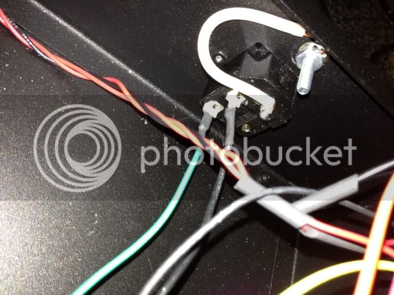
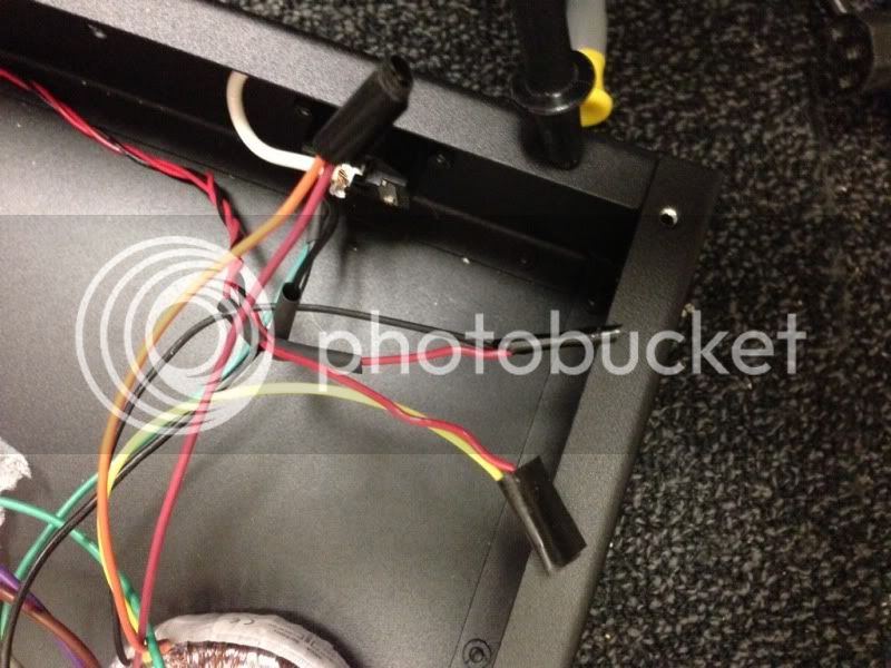
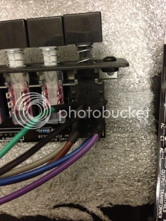
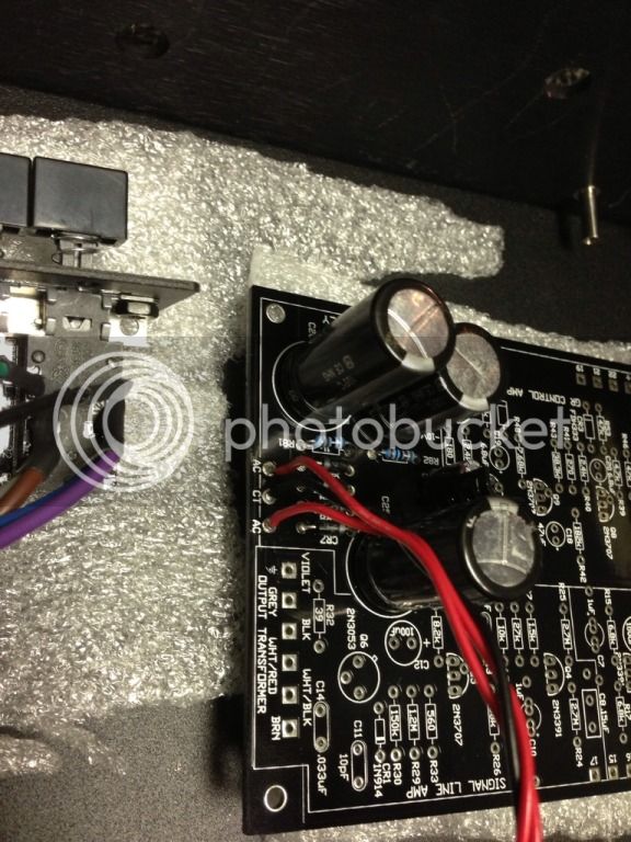
However, the voltages are still incorrect. At the 30v test point I'm only getting a very small DC number. When I test the 2 AC and the CT connection, I get around 30v on one, and 10 on the other two. Attached are pictures to double check my work.

83E33797-6EB9-4E26-81CF-92CB3BB43439-1827-0000010CDE3E0028_zps6bd8791d.jpg

7C057891-4C31-4AD3-A4BA-2E4C0A181CBB-1827-0000010CD9B6DCA4_zps566f8b1d.jpg

94D45EBD-2F19-4372-B471-61DB54A3E0CE-1827-0000010CDBD25DDB_zps8787952c.jpg

1C7FDB7C-08CF-4C28-803A-436D2936906B-1827-0000010CD6F49B4A_zps3cfdfa89.jpg
 
Because power trafos have different colours, I don't want to assume anything, but doublecheck your trafo colour coding against this:
http://web.archive.org/web/20090914070140/http://www.diyfactory.com/data/transformer_connections.gif
(split secondary +- is what you want)

on the board side, measuring the 2 red wires should give you 50v, measuring the black to each of the red should give you +/-25v. ensure your DMM is set to AC voltage at this point

 
Are you using the CT as your common ref for you black DMM lead?  You should have you common lead on the CT then test AC at each of the 25V and the 2 DC test points.
 
Echo North said:
Are you using the CT as your common ref for you black DMM lead?  You should have you common lead on the CT then test AC at each of the 25V and the 2 DC test points.

I'm embarrassed that I didn't know that... But it solved my problem!

I am however getting +/-30 AC at the board, and my 30V DC is around 36... What is the safe range?
 
No more than 10%.  But honestly even 33VDC seems a little high.

Are you using the Hairball power transformer (Avel) 2X25V?

Are your R87 R89 values correct?
 
Echo North said:
No more than 10%.  But honestly even 33VDC seems a little high.

Are you using the Hairball power transformer (Avel) 2X25V?

Are your R87 R89 values correct?

Yes to the Avel. Just double checked the resistor values at 87 & 89 and they are correct. 1.1k and 220r.
 

Latest posts

Back
Top