[BUILD] 1176LN Rev D DIY

GroupDIY Audio Forum

Help Support GroupDIY Audio Forum:

This site may earn a commission from merchant affiliate links, including eBay, Amazon, and others.
Olegarich said:
XLR OUT PIN 2 has relation to INPUT PIN2 - wave form are in same phase. 
XLR OUT PIN 3 has relation to INPUT PIN3, only wave form is much smaller and a little shifted.
Is that what you asked?
No. Transformer output is floating balanced. Your output is between XLR-pin 2 and XLR-pin3 (not between pin2 and 0V or between pin3 and 0V or whatever else reference). XLR-pin1 is connected to chassis/shield in the shortest possible way and is not involved in your measurement.
 
sintech said:
Stagefright13, this maybe helpful as a reference point.

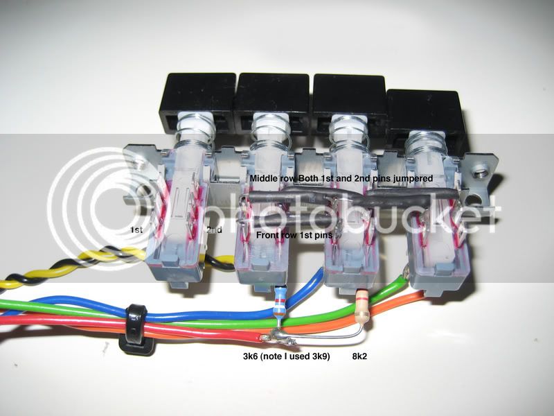
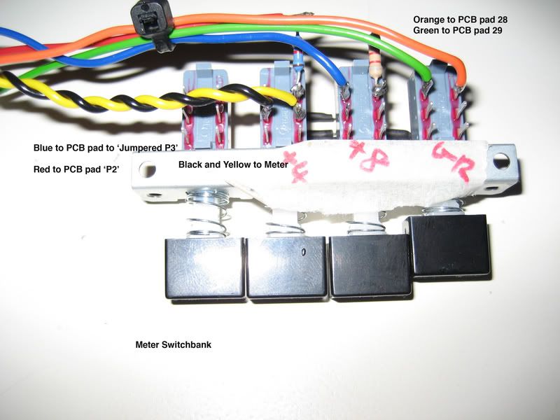
I pulled an original Urei 1176 apart and copied out the point to point for interconnects, meter and ratio switch banks. This was for the Purple MC76 so some PCB pads may be labled differently.

Purusha redrew the switchbank, and is much clearer in this format.

P2P-MC76.jpg


2MeterSwitchBank2.jpg


1MeterSwitchBank1.jpg

Hi
Someone have something similar for ratio switch?
I don't want to use the pcb...
Thanks!
 
Oh...Thanks Harpo.  Alright, so with a scope I measured incoming sine wave betwen Input pin2 and 3 and then I measured output between Pin 2-3 and they are the same.  (Only with Output Pot i can make it much bigger in out)  So it works correctly?
 
Forgive me for asking this, but what is a diode 'stud'? I read elsewhere Ed Anderson saying to heat sink it. Are we talking about the rectification diodes? I'm using the Mnats supply for a dual Rev D unit. It has the diode bridge as individual diodes.

Also, anybody have a link or search terms I need to use to find an appropriately big heat sink for the 2N3053 output transistor?

Thanks!
 
One more question. Does anybody have a recommendation or picture for a layout for a dual REV D unit that has proven to be nice and quiet?

I've seen a couple with the power transformer in the middle. You can get the transformer farther away from both boards by not putting it in the middle. So that's something I've chose to do. It's off on the right side by the IEC.  A pic of my unit is on post 5542 of this page.  The layout is a bit crazy at the moment. By the way I solved my issue from that post so it should be ignored. Happened to be input grounding.

Anyway, I'm curious about how far input transformers/output transformers and even XLR's need to be from the other channel or even from each other. ???
 
JW said:
Forgive me for asking this, but what is a diode 'stud'? I read elsewhere Ed Anderson saying to heat sink it. Are we talking about the rectification diodes? I'm using the Mnats supply for a dual Rev D unit. It has the diode bridge as individual diodes.

Also, anybody have a link or search terms I need to use to find an appropriately big heat sink for the 2N3053 output transistor?

Thanks!

The stud diode is a zener diode.  It's acts as a voltage regulator. On the older PCBs the 7824 voltage regulator is used in place of the stud diode. On the newer version we switched to the stud diode used in the original.

For the 2N3053, you need a TO39 heatsink.
Mouser Part #:
532-578305B00

Mike

 
Hey guys, I'm a total noob and not very techie when it comes to building units so I paid someone to build my hairball 1176D Rack compressor for me. It was also double checked and calibrated by reputable repair guy here in Los Angeles. However, I'm seeing an issue with the meter that I'm not sure is normal but wanted to ask the community. 

When I turn the compressor on (GR), Ratio (4), Attack (CCW) off, Input 0, Output 0 and no signal going into it. The needle hovers around 0 as expected however it starts to creep up over time and by the time I've had the compressor on for 40 mins, it's up to +1 and stays there. It doesn't seem normal to me but let me know if you've experienced this and if I should take it back to the shop. Thanks.
 
exiquio said:
Hey guys, I'm a total noob and not very techie when it comes to building units so I paid someone to build my hairball 1176D Rack compressor for me. It was also double checked and calibrated by reputable repair guy here in Los Angeles. However, I'm seeing an issue with the meter that I'm not sure is normal but wanted to ask the community. 

When I turn the compressor on (GR), Ratio (4), Attack (CCW) off, Input 0, Output 0 and no signal going into it. The needle hovers around 0 as expected however it starts to creep up over time and by the time I've had the compressor on for 40 mins, it's up to +1 and stays there. It doesn't seem normal to me but let me know if you've experienced this and if I should take it back to the shop. Thanks.

Normal.

http://www.hairballaudio.com/blog/resources/post/fetrack-operational-faq
 
Hi
I've just calibrated 2 identical units...

unit 1:
All the voltage are like Mnats rev D reference volatages

unit 2:
Q11 Drain 11.8v - Mnats 10.50v
Q13 Collector 10.50v - Mnats 9.75v
On this unit also, the meter drift 0.5 db with release pot ccw ( no signal input)
I've  calibrate the unit more times with the same results...
I've also changed all the transistos but the problem is the same..
Suggestions?
Thanks!!!


All the voltages now are ok!
The only thing is the meter, drift 1 db with release pot full CCW.
On the other unit no drifting!
Suggestions?

I've also removed the residual solder flux , but no luck...
 
ilfungo said:
All the voltages now are ok!
The only thing is the meter, drift 1 db with release pot full CCW.
On the other unit no drifting!
Suggestions?

I've also removed the residual solder flux , but no luck...

I've seen this before but unfortunately can't remember what the problem ended up being.

From what I remember, I don't recall it being a on-board component issue. I recall it being wiring related. If the release is causing the qbias to fluctuate, check all of those related parts and values.

Mike
 
Thanks Mike
I've checked,  all resistor are in right place.
all the connections are ok.
The only difference between 2 units:
when release pot is Full CCW

on bad unit
Q11 Drain go down of about 10 mv (and meter go down 1.5db, also in bypass mode)

on  good
one no change.
Thanks!
 
nobody had the same problem?
I'm going crazy!!!
Every time the drift change, now I've 5 db of drift...
Thanks!
 
I've just finished up a pair of rev D's in a case. Everything's working great and sound sexy.

However i have one small problem. The T-pad appears to be bleeding signal and not fully attenuating.

With the input and output controls both at 0 I get no signal through but if i turn the output pot up i get uncompressed signal through the output. GR meter shows no reduction.  Using it unbalanced it's a small amount but balanced it's much worse. I've triple checked the T-pad wiring and all is well.

Is this normal behaviour or is something off with my T-pads?
 
Neko Neko said:
I've just finished up a pair of rev D's in a case. Everything's working great and sound sexy.

However i have one small problem. The T-pad appears to be bleeding signal and not fully attenuating.

With the input and output controls both at 0 I get no signal through but if i turn the output pot up i get uncompressed signal through the output. GR meter shows no reduction.  Using it unbalanced it's a small amount but balanced it's much worse. I've triple checked the T-pad wiring and all is well.

Is this normal behaviour or is something off with my T-pads?

I doubt the T-Pad completely attenuates the signal. IIRC it's a 40dB pad @ 0. So with the output turned up for gain, you'll get the signal hot enough to hear.
 
I know the output transistor runs hot, but how hot is too hot? I have a top hat heat sink on it but it's still very hot. About a second is how long I can grab it.

That leads me to my next question. I have the mnats power supply with the 317/337's. Is this enough to power two REV D's?
I'll probably need to heat sink these to the chassis or something.

Which leads me to my next question. Does this look like the right substance? http://www.ebay.com/itm/20g-Tube-Syringe-Silver-Thermal-Paste-High-Performance-Heatsink-Compound-CPU-GPU-/131753508718?hash=item1ead1eff6e:g:rtIAAOSwCQZZIgqt

Also, I'm not hitting on something at mouser at the moment that has these little miscellaneous parts like the little rubber thing that isolates the screw from the to220 chip. Or the little pad that goes on the back. Does someone have a link to the little miscellanious stuff?

By the way, the Ed Anderson transformer  (with class A out) is really amazing sounding. I got a chance over a few years actually to go from these G1176 boards with a chip input and an OEP out to eventually a 600 ohm T pad/Altran input transformer with a cinemag  CMOQ output (REV F pretty much, less output gain at 1:2), to eventually just deciding to breadboard the class A output and go full REV D. So, now it's gonna be a stereo REV D. Just sounded right to me.  Still would like to hear the REV F with the Ed Anderson for the A/B output.


Hairball Audio said:
I doubt the T-Pad completely attenuates the signal. IIRC it's a 40dB pad @ 0. So with the output turned up for gain, you'll get the signal hot enough to hear.

Thanks for confirming this Mike!

Here's some shots of my finished build.


Attachments

  • IMG_2596.jpg
    IMG_2596.jpg
    1.3 MB · Views: 33
Back
Top