[BUILD] 1176LN Rev D DIY

GroupDIY Audio Forum

Help Support GroupDIY Audio Forum:

This site may earn a commission from merchant affiliate links, including eBay, Amazon, and others.
Hi guys,

Quick question about the PSU section: Can I substitute the same tantalum cap that goes in C19 and C20 (Kemet 50v, 6.8 uF, 80-T350F685K035AT on Mouser) for C23, which is supposed to be an electrolytic 6.8uF, 35v?

According to the tantalum wiki, they're frequently used in PSUs, but I figured I should check.

thanks!
Matthew

edit: I had to order some stuff from Mouser anyways, so I'll just go with an electrolytic.
 
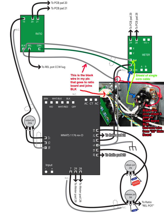
one more (in fact two), rev D is born, nothing special about the case ( tat's case), but i try to be meticulous for the wiring, many many thanks to Mnats, the board is just perfect to understand the different stage and so clear to solder component, ed anderson for the recreation of the transformers, hairball for the easy to get hard to find component, skylar for his wiring sketch, and of course jakob, as always

http://jardinprive.free.fr/image/1176/1176-01.jpg
http://jardinprive.free.fr/image/1176/1176-02.jpg
http://jardinprive.free.fr/image/1176/1176-03.jpg
http://jardinprive.free.fr/image/1176/1176-04.jpg
http://jardinprive.free.fr/image/1176/1176-05.jpg
http://jardinprive.free.fr/image/1176/1176-06.jpg
http://jardinprive.free.fr/image/1176/1176-07.jpg
http://jardinprive.free.fr/image/1176/1176-08.jpg
http://jardinprive.free.fr/image/1176/1176-09.jpg
http://jardinprive.free.fr/image/1176/1176-10.jpg
 

Attachments

  • 1176-01.jpg
    1176-01.jpg
    26.4 KB
thank you

if it's the one to switch off compression

22 from board to common on spdt,
off position contact (check it with ohmmeter) gnd from the ground board, near 22
on position contact, to ratio board attack pot (GRN)
 
ilfungo said:
Camel compliments great job!
you could tell me how you connected SPDT?
Thanks
wireCheck3.jpg
 
Thanks Kamel and Canidoit
now everything seems to work well! Tomorrow I will test
thanks again ;D

The only problem I have is one of the two compressors, if I put the output  pot CCW  the meter go
to +3 (if disconnected XLR output returns to zero).
you know what can be?
 
The only problem I have is one of the two compressors, if I put the output  pot CCW  the meter go
to +3 (if disconnected XLR output returns to zero).
you know what can be?

check your transformer wiring and calibrate the comp, it may be an issue
 
Team,

can I use 1n4003 in the PSU section of the Rev A and D? Or must I use 1n4004?

I have loads of 1n4003!!!!! Will it make a difference?

Thanks in advance

Michael :)
 
Hi to everyone,
i can't understand what's going on with the last 1176 rev D i made.
it works almost as it should but there is a bad distortion increasing with the gain reduction JUST on low frequencies. i mean, the more it compress low freq the more distortion appears. in bypass mode everything's ok and there is NO distortion if i get out the FET in GR mode as well. i changed a lot of 2N5457,checked for dry soldered pins,checked the values with another board which is properly working,  calibrated hundred times but it's still just a nice bass guitar fuzzbox. i made another unit and that is perfect. if somebody knows....let me know!  thanks a lot, bye!!  sandro
 
I just finished 2 Rev. D ;D
they sounds fine and the stereo connection works ...
I want to say thank Mnats, Echo North, Mac, Canidoit, Kamel and this wonderful forum, without you I could never ...
GRAZIE!!!!!!!

I'll put the photos as soon as possible
 
my rev A & D
thanks

Sorry, the problem that I said I still have it on one rev D (pot ccw out everything - meter planted in full scale) and I noticed that happens when warm and cold are reversed pole ( XLR out)
I rechecked all the wiring and everything is fine??
What can it be?
THANKS!


it's normal that rev A have more output of rev D with the same transformer (in&out)?
 

Attachments

  • 2 x Rev A + 2 x Rev d.jpg
    2 x Rev A + 2 x Rev d.jpg
    74.8 KB
ilfungo said:
Thanks Kamel and Canidoit
now everything seems to work well! Tomorrow I will test
thanks again ;D

The only problem I have is one of the two compressors, if I put the output  pot CCW  the meter go
to +3 (if disconnected XLR output returns to zero).
you know what can be?


Hi guys
some of you have had a similar problem?
I ask you to help because I rechecked all connections and do not know what else to do  ???
 
greetings,  this is my first post to this thread.  i've avoided it because i have a friend helping me and because it's a little intimating here.  i have searched the boards for an answer to my question and i'm not finding anything definitive.  sorry in advance if i missed anything.

i have a question about the output transformer wiring to the board.  i'm using the complete hairball kit for this build.  i mistakenly wired my board according to this configuration:
http://cedub.com/pub/1176/SG-1176-RevD-OUTPUT-Wiring.jpg
the colors listed on this diagram do not match up at all with what is printed on the PCB - that is, the order is wrong.  it's my bad for not double checking this.  i'm using terminal blocks so the silk screen was covered up.  still, i did have a print out so again, my bad.

when powered it up, i fried R32.  i have a second board all stuffed and ready to go so i'd like to try that one out with the correct wiring.

my question is this.  are the labels on the PCB correct for use with the hairball output transformer?  my PCB is labeled "v2.2 26.01.09".  the board shown in the "v2 building" document on mnats Rev D page is dated 30.04.08. 

Thank you in advance for any advice.

- chris
 
Sounds like you have V2.

http://mnats.net/files/DIY1176LNREVD_V2.pdf

You'll have blue, red, orange and yellow left over.  Orange and yellow get tied together and red and blue go to the xlr out.

Oh and replace R32.

Thanks,

Mike
 
Yes just tie them together.

If you look at the original schematic, you will see by connecting them you are wiring two of the secondary windings in series.

Mike
 
Hi guys
what type of pot can be used for zero adjustment from the front panel?
I found a potentiometer wire to 2 K multiturn,  can fit?
thanks
 
Kamel said:
check your transformer wiring and calibrate the comp, it may be an issue

I was just looking at the pic of your completed unit and noticed that the label on the Altran is pointing the opposite way as mine. The label on mine is pointing towards the H-Pad links.

I put mine the way it is because that way the dot on the label lined up with the "Altran 1" arrow - was yours on the opposite side?

My pcb is the 07/04/07 edition.

Perhaps I've just put it in backwards - I haven't soldered that in, so now is a good time to make that kind of mistake.
 
i don't use the mnat's transformer pcb, but the hairball audio one and on the mnat pcb , the dot (pin one) is near the Hpad option
 

Latest posts

Back
Top