[BUILD] CAPI VP28~500 Series~2-Stage Preamp~Official Support Thread

GroupDIY Audio Forum

Help Support GroupDIY Audio Forum:

This site may earn a commission from merchant affiliate links, including eBay, Amazon, and others.
Hey guys...I've built a VP28, but I'm running into a head scratching problem. The input gain works fine, but the Output fader is working in an "off and on" fashion." When the output fader is switched to 8, the signal passes. Before that, no signal. Turning it to 10 and 12 gets it no louder, it just seems to turn on at 8. I figured it could have been a cold solder or something on the fader, but I've touched up, resoldered, and I'm still getting the issue.

I've checked for continuity - I'm a newbie, so please cut me a little slack...I get readings on all the points, but some read really quickly and then go to open loop. Didn't know if that was common or not. I'd be shocked if it's a cold solder - I've checked it 20 times and they all look fine. Could it be a bad switch? I know that's pretty unlikely...
Anyway, any help would be appreciated.
 
Hello,


as said in the other thread please check if the switch has stop pins or not.Easy to set them wrong when the shaft was not in the correct position while inserting.
Also check if all fader resistors are in the right place.Sometimes they are misread and swapped.


Best regards,


Udo.
 
kante1603 said:
Hello,


as said in the other thread please check if the switch has stop pins or not.Easy to set them wrong when the shaft was not in the correct position while inserting.
Also check if all fader resistors are in the right place.Sometimes they are misread and swapped.


Best regards,


Udo.

Thanks, Udo. Don't believe there are any stop pins in the new builds.
 
Commander Fluffypants said:
I appreciate the response, but it's not down to drummer level...

First of all, I have no idea how I'm supposed to have something in the jig and probe the card edge at the same time.

I need to be told physically where to put the probes. The RevA.2 PDF tells me where to put one of the probes, but I'm not sure which one. The other probe goes to ground. Great. Where is ground? On the card edge that's in the jig? The one labelled "audio ground" or the one labelled "PSU Ground"? Makes no sense. There's got to be ground somewhere on the board or maybe somewhere else altogether.

But also, I'm really, REALLY curious to know if the one particular symptom where phantom power toggling on OTHER pres causes THIS pre to pop tells us anything at all about the nature of the problem.

Hello.

As it has been said before on this forum by people far knowledgeable about life and electronics than I, there are several things that are assumed the end user already knows how do, one of which is how to use a multimeter. If not, one would need to do some Internet searches on the subject. It's not meant to be demeaning at all, but to encourage one to do research and search out information for one's self. I've asked numerous questions when I first started learning that went unanswered and I had to just stay at it till I found the answer to problems with builds.

As of for the popping, have you tried this preamp in a different rack? Do the rest of the preamps pop when you engage phantom on any other channel? The Radial boxes have the feed switch to make channel strips. Are any of those engaged? That would make the most sense in this scenario. If that is not the case, you will have to take your multimeter and look up API 500 series pinout and look at the VP28 overlay on CAPI's website. Pull the op amps. Negative/Common Probe on ground of the edge connector. Positive probe one at a time on the DOA connectors and see if there is any difference when you engage +48V on a different preamp. Do the same to the output on the edge connector. Same with DOAs installed. Another thing to look at is with just the extension jig plugged in and no VP28 measure to see if there is difference in voltage between In+ and ground and In- and ground. Somehow voltage is making its way to input or output from another slot. Your VP28 might be fine after all.

Good hunting.

Thanks!

Paul
 
Johnkenn said:
Hey guys...I've built a VP28, but I'm running into a head scratching problem. The input gain works fine, but the Output fader is working in an "off and on" fashion." When the output fader is switched to 8, the signal passes. Before that, no signal. Turning it to 10 and 12 gets it no louder, it just seems to turn on at 8. I figured it could have been a cold solder or something on the fader, but I've touched up, resoldered, and I'm still getting the issue.

I've checked for continuity - I'm a newbie, so please cut me a little slack...I get readings on all the points, but some read really quickly and then go to open loop. Didn't know if that was common or not. I'd be shocked if it's a cold solder - I've checked it 20 times and they all look fine. Could it be a bad switch? I know that's pretty unlikely...
Anyway, any help would be appreciated.

I've been shocked how many times I didn't think it was a cold solder joint/misplaced/mis-wired component and it turns out to be just that.

Get some solder wick, remove as much solder as you can and reapply. If you're not already, use the very small solder so it melts and flows easier. If you think it is the switch, you can measure continuity between the pole and each of the pins per switch position to verify it it. You will still have to remove some of the solder first to ensure you are making contact to the pin and not the solder.

Thanks!

Paul
 
Potato Cakes said:
As it has been said before on this forum by people far knowledgeable about life and electronics than I, there are several things that are assumed the end user already knows how do, one of which is how to use a multimeter. If not, one would need to do some Internet searches on the subject. It's not meant to be demeaning at all, but to encourage one to do research and search out information for one's self. I've asked numerous questions when I first started learning that went unanswered and I had to just stay at it till I found the answer to problems with builds.

Thank you, Paul. The problem with not knowing things is that you don't know what you don't know. Of course I've looked up all sorts of things, but if I don't know what I should be looking to learn, it's hard to find it. As you can see, it's hard to even know what I'm asking for. What does help is when Jeff specifically tells me to test the thing out of the jig, with no power, or when you describe testing it with the DOA's out.

Potato Cakes said:
As of for the popping, have you tried this preamp in a different rack?

No, but I've tried it in different slots in this rack. All symptoms described are the same no matter what slot it's in.

Potato Cakes said:
The Radial boxes have the feed switch to make channel strips. Are any of those engaged? That would make the most sense in this scenario.

No, they are not. Yes, I double checked. And triple checked.

Potato Cakes said:
If that is not the case, you will have to take your multimeter and look up API 500 series pinout and look at the VP28 overlay on CAPI's website. Pull the op amps. Negative/Common Probe on ground of the edge connector. Positive probe one at a time on the DOA connectors and see if there is any difference when you engage +48V on a different preamp. Do the same to the output on the edge connector. Same with DOAs installed.

OK, bear with me a second... I can't tell if the unit is supposed to be powered for these tests. I can't probe the card edge while it's under power and engaging phantom on another unit won't have an effect if it's not plugged in.

And when you say "ground," in this case it's gold finger #5? Or is it #13? 5 makes sense to me because we're testing the audio path... *I think*...
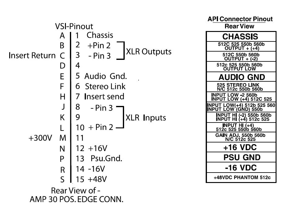
VSI-API-Pinouts.JPG


Now, when testing the DOA connectors, there are six for each DOA. Am I to probe all twelve of these or is it understood that I'm only probing certain ones?  It seems possible to me that I wouldn't be probing the power connectors and I'd just be probing the audio path, and that if this test is supposed to be done under power (which I still don't understand how I'd probe the card edge while under power) it seems that there could be a considerable amount of voltage difference between these connectors, and that could have implications for my DMM settings or safety. (This is the area where I don't know what it is I don't know, and I don't know how to find out what I don't know because I don't know what it is that I don't understand. I know that's a ridiculous sentence, but I'm trying my best to describe things as I perceive them so someone can identify where my deficit is.)

Next  question about probing the DOA's and the DOA connectors:

Do I do it from the underside of the board?  Does it matter? (Shouldn't as far as I can tell...) If I'm probing the card edge, the underside will be up and the connectors will be easily accessible from the underside.

What do you mean by "Do the same to the output on the edge connector"? Test from ground to the output or from each DOA connector to the output? And WHICH output? Reading the API pinout, I see three. I get that they correspond to the XLR pins, but I'm not sure which one is the correct one for this test.

Potato Cakes said:
Another thing to look at is with just the extension jig plugged in and no VP28 measure to see if there is difference in voltage between In+ and ground and In- and ground. Somehow voltage is making its way to input or output from another slot. Your VP28 might be fine after all.

This is testing the Workhorse? Hasn't that been ruled out when we know that the behavior is identical in multiple slots?

Thanks again and apologies again for questions that might appear to be stupid. Once I get a grasp on some this stuff that's obvious to others, I'll be able to ask questions from a better informed position in the future...


Potato Cakes said:
I've been shocked how many times I didn't think it was a cold solder joint/misplaced/mis-wired component and it turns out to be just that.

Get some solder wick, remove as much solder as you can and reapply. If you're not already, use the very small solder so it melts and flows easier. If you think it is the switch, you can measure continuity between the pole and each of the pins per switch position to verify it it. You will still have to remove some of the solder first to ensure you are making contact to the pin and not the solder.

Thanks!

Paul

I solder-sucked every pin joint on the input and fader switch and re-soldered with Kester solder. Still the same thing. I did check for continuity by starting with the -20 pin and t4 test point. I switched the switch and moved consecutively. At each point I would end up with a 0 reading...which I think is correct, right? I was connecting the MM pole to the solder instead of the pin, so maybe I'll try again.
I've triple checked that every resistor is in the right place. Every cap is turned correctly. Output transformers are wired correctly (Double checked the Litz to 2623 configuration)...I'm at a loss.
 
Commander Fluffypants said:
Thank you, Paul. The problem with not knowing things is that you don't know what you don't know. Of course I've looked up all sorts of things, but if I don't know what I should be looking to learn, it's hard to find it. As you can see, it's hard to even know what I'm asking for. What does help is when Jeff specifically tells me to test the thing out of the jig, with no power, or when you describe testing it with the DOA's out.

No, but I've tried it in different slots in this rack. All symptoms described are the same no matter what slot it's in.

No, they are not. Yes, I double checked. And triple checked.

OK, bear with me a second... I can't tell if the unit is supposed to be powered for these tests. I can't probe the card edge while it's under power and engaging phantom on another unit won't have an effect if it's not plugged in.

And when you say "ground," in this case it's gold finger #5? Or is it #13? 5 makes sense to me because we're testing the audio path... *I think*...

You can just use the Chassis for reference if you want. Or any of the other ground connections.

Commander Fluffypants said:
Now, when testing the DOA connectors, there are six for each DOA. Am I to probe all twelve of these or is it understood that I'm only probing certain ones?  It seems possible to me that I wouldn't be probing the power connectors and I'd just be probing the audio path, and that if this test is supposed to be done under power (which I still don't understand how I'd probe the card edge while under power) it seems that there could be a considerable amount of voltage difference between these connectors, and that could have implications for my DMM settings or safety. (This is the area where I don't know what it is I don't know, and I don't know how to find out what I don't know because I don't know what it is that I don't understand. I know that's a ridiculous sentence, but I'm trying my best to describe things as I perceive them so someone can identify where my deficit is.)

You need power to the unit to test voltage...

Leave your common probe connected to ground (which ever you chose). Take your +/V (how ever your meter is labeled) and test all the DOA with the op amps pulled pins and make sure you are getting +/-16V (or close to it) on the +/-V connections and then measure what you are getting for the rest of the pins (follow the DOA pinout on the VP28 Overlay). Then do the same thing with +48V. Then do it again while switching +48V on an off.

Commander Fluffypants said:
Next  question about probing the DOA's and the DOA connectors:

Do I do it from the underside of the board?  Does it matter? (Shouldn't as far as I can tell...) If I'm probing the card edge, the underside will be up and the connectors will be easily accessible from the underside.

What do you mean by "Do the same to the output on the edge connector"? Test from ground to the output or from each DOA connector to the output? And WHICH output? Reading the API pinout, I see three. I get that they correspond to the XLR pins, but I'm not sure which one is the correct one for this test.

This is testing the Workhorse? Hasn't that been ruled out when we know that the behavior is identical in multiple slots?

Thanks again and apologies again for questions that might appear to be stupid. Once I get a grasp on some this stuff that's obvious to others, I'll be able to ask questions from a better informed position in the future...

Doesn't matter if it on the underside. Which ever way is easiest.

Test all of the output connections. The two on the DOA and the two on the edge connector. Jeff's design doesn't use the third one (look at VP28 PCB and compare it to the API pinout).

I'd still test the workhorse. Just to be certain.

Like I said, if the VP28 channel is popping when you engage phantom power on a different module, voltage is some how getting to it's input to the the output XLR.

You could also measure the output XLR of the VP28 when +48V is engaged. You will have to do a search for how +48V connects to an XLR if you haven't already.

Good Luck.

Thanks!

Pau
 
Johnkenn said:
I solder-sucked every pin joint on the input and fader switch and re-soldered with Kester solder. Still the same thing. I did check for continuity by starting with the -20 pin and t4 test point. I switched the switch and moved consecutively. At each point I would end up with a 0 reading...which I think is correct, right? I was connecting the MM pole to the solder instead of the pin, so maybe I'll try again.
I've triple checked that every resistor is in the right place. Every cap is turned correctly. Output transformers are wired correctly (Double checked the Litz to 2623 configuration)...I'm at a loss.

If you are getting 0 (some meter beep when selected for continuity) between the pole and each corresponding switch then the switch is fine. Are you getting continuity between any of the adjacent pins? If the switch is fine then either a connection between the switch position and it's resistor or the resistor to where ever it goes next (I can't remember if it goes to Q1 or the one of the op amps, you'll have to ask Jeff).  Don't give up just yet. I've had projects sitting around for a year that I couldn't find the problem and then it wound up being a simple mistake.

Thanks!

Paul
 
Thanks again, Paul. I've been reading your last response for the past two days and I almost understand it... or rather I understand most of it. Mostly, I just don't know where I'm supposed to put the black probe while I stick the red probe in all those places.
 
Hi there,

I just put together my first (of four) VP28. I've been building several 500 series preamps before, but this is the first time I got the famous magic smoke once I put it in my lunchbox  :eek:

As far as I can see, I fried PR2 and PR4 and would like to ask for suggestions where I should start troubleshooting. I use gar1731 (V4.1) opamps which I also assembled myself.  The smoke appeared once I installed the opamps, i.e. without the opamps at least nothing obvious went wrong, though I didn't check any voltages. Apparently, this was too much self-confidence which was fatal  :-[

Should I try reconnecting without opamps and test any voltages or can I create further damage by doing so? Any help is appreciated!

Cheers,
 
If there was no smoke without DOAs, then smoke with DOAs.....


You should have some DOAs that you bought instead of built for this very purpose.

DOAs.


Thanks!

Paul
 
I have a pair of gar2520 DOAs from a previous build that worked flawlessly up to now. I could use those.  But before  installing them, I would like to make sure that there is nothing wrong on the main PCB, in order to avoid further damage.
 
Replace any burnt out resistors connect without op amps and measure voltages on the DOA sockets. If those are fine then you should be safe to install your working gar2520s. The PR resistors are there to project anything downstream in case improper voltages going to inappropriate places inappropriately.

Thanks!

Paul
 
Should I check only the 16V supply voltages, i.e between C and +V/-V or anything else before installing the gar2520s?
 
OK, I swapped the fried resistors by new ones.
Before connecting to the power source, I measured the resistances between the DOA sockets as described in the VP2x Assembly Guide. Most of them seem too low:

Preamp DOA position:
-V to +V:  35.8 kOhms
-V to C: 31.8 kOhms
+V to C: 4.1 kOhms
C to O: fluctuating > 250 kOhms
+V to O:160 kOhms
-V to O: 11.4 MOhms

Fader DOA position:
-V to +V: 35.8 kOhms
-V to C: 31.5 kOhms
+V to C: 4.1 kOhms
C to O: out of DMM range
+V to O: out of DMM range
-V to O: out of DMM range

I conclude that the (or at least one) problem is on the main PCB. Any suggestions where to look first?

When connected to power (without DOAs installed) I measure +-15.8 V at all -V/+V terminals.
I also noticed that on one of the DOAs R14 and R15 (10 Ohms) are burnt as well, I that is useful info.

Thank you for your help!
 
Good news: with the 2510s the preamp seems to work fine in a first test. I presume the culprit is one of the 1731 DOAs, probably the one with the burnt resistors. Any suggestions on how to further narrow it down?

And is there a way to test opamps without installing them? I would like to avoid a scenario like this for the upcoming builds (still 3 x VP28 and 2 x VP312 to do  ;D)
 
OK, I finished my 6 additional modules +12 DOAs. All of them are working except the one gar1731, which I still haven't figured out what the problem was. Luckily, I had ordered a few spare DOA kits  :)

One thing that I noticed though with the VP28 modules is that once I power off the lunchbox, the VP28 sends out a nasty sweep signal to my sound card. This happens with all four VP28 modules and with none of the VP312 (or any other 500-series preamp I own). I tested with a BAE 6-slot lunchbox as well as a 11-slot rack by VanDaal Electronics. Is this the normal behavior?

Apart from that, I'm up for testing now once all modules are installed  ;D
 

Attachments

  • CAPI.jpg
    CAPI.jpg
    148 KB
Back
Top