[BUILD] CAPI VP2X~500 Series~Preamp Kit~Official Support Thread

GroupDIY Audio Forum

Help Support GroupDIY Audio Forum:

This site may earn a commission from merchant affiliate links, including eBay, Amazon, and others.
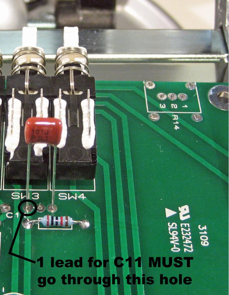
hey surfcat - the placement of C11 is wrong... not that that makes a huge difference. should be one hole over, where the line is.

haven't had a chance to look further than that...

happy new year!
 
i wonder if soldering the t-pad directly to pcb will help to avoid mistakes...
I'm sure it can be done on a dual layer pcb..
 
Hey surfkat,

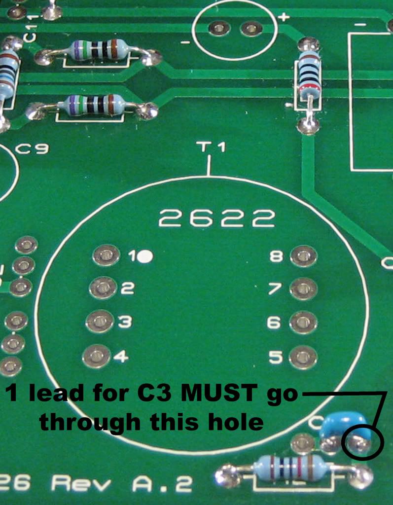
I noticed the same as haima with C11. C3 is also in the wrong position.

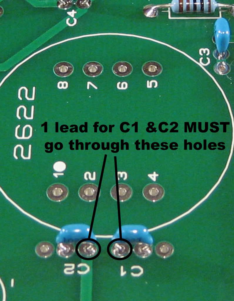
I have posted some pics regrding those caps and also C1 and C2 since they will accommodate a 2.5mm or 5mm lead spacing. The signal track must be connected too or those caps will do nothing. these are some pics from the upcoming VP2x Assembly Guide that I am nearly done with.

Anyhow, here's C3 details.
C3closesmaller.jpg


Here is C11 details.
C11close.jpg


And here are C1 and C2 details.
C1andC2closesmaller.jpg


Like haima said, I'm sure these things are not you problem but they do need to be corrected.

Cheers, Jeff
 
3nity said:
i wonder if soldering the t-pad directly to pcb will help to avoid mistakes...
I'm sure it can be done on a dual layer pcb..
Yes, this is true. Actually my friend Hairball Mike has a solution for this that I will probably offer too. Still, flying leads shouldn't be too much of an issue for a DIY'er!  ;D
 
surfkat, your t-pad looks to be wired correctly although I think the black lead to the t-pad solder lug could made a little more stout.
 
jsteiger said:
3nity said:
i wonder if soldering the t-pad directly to pcb will help to avoid mistakes...
I'm sure it can be done on a dual layer pcb..
Yes, this is true. Actually my friend Hairball Mike has a solution for this that I will probably offer too. Still, flying leads shouldn't be too much of an issue for a DIY'er!  ;D
don't make it too easy ;D ;D ;D
more complicated builds wouldn't have a chance anymore :eek: :eek: :eek:
no, we won't offer the PoorMan with pre build or PCB mounted attenuators!
 
[silent:arts] said:
3nity said:
I dont mind but but some people cant even solder caps in its right place...
those people will learn and grow with it :)

Definitely DIY is just a learning process, and this is a simple project and besides the Opamp where you need to have a good (small tip) soldering iron and soldering skills, this project is perfect for people to learn.

The T-Pad wiring with Jeff's document is a breeze. no tricks in there

 
OK surfkat, here a few things for you to check.

I did some quick tests using an MR1 signal generator and a Fluke 177. No power connected to the PCB and no DOA in the sockets.

Apply a balanced sine wave signal to the + and - inputs of the PCB, pins 8 and 10. I set the level to -12dbu. I then get a reading of 161.7mv/ac when probing between pins 8 and 10 of the PCB. It's a touch low due to the MR1 driving the load of the preamp. The reading when probing between the "+" DOA socket and the "C" DOA socket is 1.1v/ac. There should be no significant reading between the "-" DOA socket as it is only for feedback gain control of the DOA. The signal is unbalanced(by the 2622) when entering the DOA and only enters the non-inverting side. A very similar reading will be obtained from probing between pins 5 and 8 of the 2622.

If you don't get a similar result, you will probably and end up desoldering the 2622 for a quick test. The 2622 has a voltage gain of about 16.9dbu(1:7). When applying a -12dbu signal to the paralleled primaries of a 2622 (connect "+" to pins 1 and 2, connect "-" to pins 3 and 4), probing between pins 5 and 8 will give you an approximate reading of 1.353v/ac. 1.377 is +5dbu so, nearly 17db of resulting gain.

Hope this all helps in some way.
Jeff
 
Hey guys,

I have just finished the step by step, detailed assembly guide for the VP2x projects. I have a link in the first post of this thread and will soon have it on all the relevant pages over at my website. It is more geared toward a newbie DIY person but hopefully a little something for others too. Open the link and save to your computer.

VP2x Assembly Guide.pdf

Let me know what you think.

Cheers, Jeff
 
Congratulations Jeff,
I read the document and I think it's great.

even someone that never touched a soldering iron will be able to do your project.

more experience people can also use it for reference while building also,
making the process not only faster but slicker!


Latest posts

Back
Top