[BUILD] fripholm's TG1 Zener Limiter boards - support thread

GroupDIY Audio Forum

Help Support GroupDIY Audio Forum:

This site may earn a commission from merchant affiliate links, including eBay, Amazon, and others.
innercityman said:
Yeah, I visited their page when searching infos on the TG1 and I wondered what's the difference between their TG1 kit and Fripholm's one ?

It seems the switches are on PCBs, so you would be committed how you want to do your panel layout. My thought is that if someone wanted these style of meters but were unsure about making the VU version work, then this would be a faster way to get DC mA versions than to order custom from Sifam.

Thanks!

Paul
 
JCN1218 said:
Concerning the illuminated push button bypass wiring. I saw in an earlier post something about using a relay to trigger the bypass and wiring the led to one side of the switch. I've never worked with relays before. If anyone would be willing to explain that setup a little more in detail or perhaps post a crude wiring diagram it would be highly appreciated.

I've just updated the guide with a wiring diagram. Just re-download (link in first post) and see page 2 of the guide.

My relays are mounted on perf board with a 2.54 grid, powered directly by the +28Volts from the PSU board - GND also directly from there, not the limiter board. Most relays can operate at up to 150% of their rated coil voltage, so a 24V relay should be fine. In this case I preferred to power the relay when in Bypass. This way, no current is drawn in normal operation, which could lead to higher supply ripple. Don't forget the flyback diode in parallel to the coil.
 
Potato Cakes said:
I still haven't been able to order the correct power transformer to power up my build

Paul, have you seen this: https://www.alliedelec.com/block-usa-rkd-60-2x30/70632313/
 
Thanks so much guys! I'm definitely learning a lot building this project, it's been a blast so far. Can't wait to have it up and running
 
fripholm said:
Paul, have you seen this: https://www.alliedelec.com/block-usa-rkd-60-2x30/70632313/

I have not. I was going to just order the Hammond, but I this would be a much better option. I'm just waiting till I get back. I head over on that side of the pond for 9 days then I'll be able to get back on this upon my return.

Thanks for the info!

Paul
 
innercityman said:
Yeah, I visited their page when searching infos on the TG1 and I wondered what's the difference between their TG1 kit and Fripholm's one ?

There are more options for switching iron in and out or having op amp based balanced in and out.  Essentially it is an i/o board with bypass and relays on to perform this switching.  It's quite a tricky board to get your head round if for example you want op amp in & transformer out permanently.  It also has options for the hold function on elma switches.  You can build it like an original TG or the chandler version.

(you might ask whey you would want to swiitch the iron out.  I used Gardners transformers & there is not a massive difference between either option)
 
So while I wait on parts, I tested to see if the meters I acquired were indeed of the VU variety, but it seems they are DC meters. Whether they are 1 or 2.4mA I do not know (Don Audio lists them as replacements for the Chandler Limiter meters). But I do know that they do not respond to AC current coming direct from my signal generator, except I can actually hear the 1kHz tone in the meter itself. I did this same test with a known VU meter and the needle responded as expected. If I get the inclination I'll open up a GSSL and test that circuit with these meters and see what happens. So we may not have to much of anything to get these to track correctly with the TG1 boards.

Thanks!

Paul
 
That would be awesome news! Thanks for going the extra mile Paul, keep us posted

Edit:
I emailed Frank from Curious Audio, the site selling the DC mA sifams you had linked to. If the Don audio meters are the same, then they are 2.4 mA meters.
 
All righty, here's what I have found.

I connected the Sifam to the GSSL and it is indeed a DC meter, but I believe it is 2.4mA. The scale is also curious as there is an indicator line below 0 on the scale, and there is not enough movement on the mechanical zero adjustment to get it up to that "0" mark.

The signal I used to get 8dB of reduction on the 1mA meter hits about 2dB on the Sifam (with the needle resting at the mark below "0"). This is part of the story where I don't know exactly how to proceed as I am not familiar with the history of these units or how they behave. It still may track better with this TG1 circuit, but I won't be able to test any of that for another week. I don't know if using a VU driver will still help solve this problem. Maybe there is are some things that can be swapped out in the metering section of the boards to make it work better with the Sifams.

Okay, you guys' turn...

Thanks!

Paul
 
@TwentyTrees
TwentyTrees said:
LOVE that design - sleek! Those toggle switches work really well, is there a link you can share?
Thanks. :)
Yeah, also like the toggle switches. These are from Miyama.
Currently doing the Design in Illustrator and C4D.
When i´m sure i will port this to a frontpanel-designer layout.


@Paul
Potato Cakes said:
Okay, you guys' turn...
R91/R92 is good start i think.
Lower R91 and/or R92 may can help to fix this issue.

Don´t know how much, just an idea.
 
Potato Cakes said:
Okay, you guys' turn...

In addition to what ToBSn said, try two diodes in series instead of just D15. This increases the voltage drop through the meter's resistance and raises the current - in theory (LTSpice, that is)  ::)
 
New layout – in stereo...

Took´s 3 hours to render on my 9 years old machine.  :eek:
 

Attachments

  • ZenerII5.png
    ZenerII5.png
    1.3 MB
fripholm said:
In addition to what ToBSn said, try two diodes in series instead of just D15. This increases the voltage drop through the meter's resistance and raises the current - in theory (LTSpice, that is)  ::)

I'll definitely give these changes a whack and see what happens.

I did reach out to Sifam about this and they said they could make these meters 1mA if need be (same model and layout). Lead time would be 5 weeks. I'm still over on the other side of the pond at the moment, but as soon as I get home I'll be able to mess around with the resistor and diode suggestions. If I can't figure something out I'll just get order new ones from Sifam.

Thanks!

Paul
 
Power transformer just arrived today, and I got an email from Sowter that my in/out transformers are on their way! Can't wait for them to arrive so I can finally power up and test this compressor. Hopefully we can get these meters to work since I already have the pair of them. Nice to know that Sifam offers the 1mA version though if all else fails.
 
Powered up today for the first time, got my PSU to the proper voltage output without problems. Unfortunately when I try sending a test tone through, I get no output. I feel like signal isn't even reaching the board. I double checked my bypass switch and switched it on and off a few times, but still nothing. Any ideas?
 
JCN1218 said:
Unfortunately when I try sending a test tone through, I get no output. I feel like signal isn't even reaching the board. I double checked my bypass switch and switched it on and off a few times, but still nothing. Any ideas?

I'd definitely start to double/triple check the wiring. The bypass switch connects the input transformer with the output stage (when bypass is switched in), which means that the output stage is always in the signal chain. If there's no output, something is wrong there. Do you have an oscilloscope to trace the signal? Makes things much easier.  :)
 
fripholm said:
I'd definitely start to double/triple check the wiring. The bypass switch connects the input transformer with the output stage (when bypass is switched in), which means that the output stage is always in the signal chain. If there's no output, something is wrong there. Do you have an oscilloscope to trace the signal? Makes things much easier.  :)

I have an oscilloscope in my DAW, although I'm not sure how to use it to trace the signal. I checked my switch wiring again and thought I had found the problem. I'm using the push-buttons from don-audio, currently without the lights and relays since I'm waiting to find out what resistors I'll need before placing another mouser order. Anyway, I had initially thought that the tabs labeled C were the poles, but I think I was mistaken, so I just fixed it. I'm still not getting any output. I'm very confident that the wires from the switch to the board are correct at this point. Maybe the switch is bad?
 
Measure the switch with DMM. This will resolve any questions regarding where is what contact.
 
JCN1218 said:
I have an oscilloscope in my DAW, although I'm not sure how to use it to trace the signal.

Don't just use your interface's line inputs, the DC in some spots could hurt your interface and/or speakers if you're not careful.

I have a cheap USB oscilloscope from PICO (about 120 bucks). One of the best investments I've ever made. You'll learn a lot just by (carefully) probing around in circuits. And there are even cheaper alternatives that do the job quite well. Do a search here, this topic comes up frequently.

For now just follow Ilya's advice and check continuity with your DMM, so you can rule out the switch as the problem.

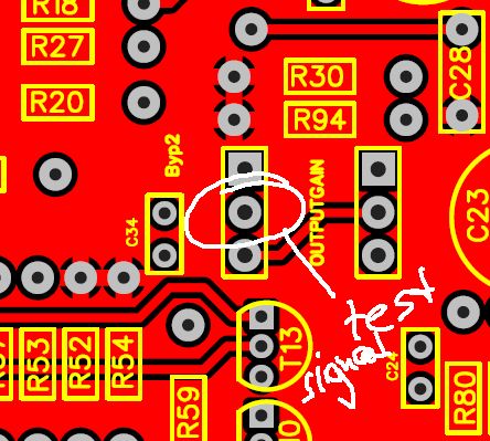
You could also inject your test signal directly into the pad pictured below. It shouldn't have DC on it (measure it to be sure).

outputstagetest.jpg


This bypasses the switch and output pot completely and goes directly to the output stage, to allow you to check if it's working properly.
 
Thanks for the advice everyone!

I think I may definitely have to invest in an oscilloscope, although in the coming days I'll see what I can do to get this thing working without one.

I did check the switch the other night. It does work, and I actually had it wired up correctly the first time. I tend to get ahead of myself with trouble shooting, so now I'll have to go fix the switch wiring again.

I'll have to check my switch wiring again, I feel like I must have it wired incorrectly but I just can't see my mistake. Maybe I'll have a friend or my dad take a quick look at it. Fresh eyes are usually a big help.

I'll be sure to try putting the input signal right into that middle pad as well if I still can't figure out the switch.
 

Latest posts

Back
Top