Build Thread:VECA MS (VCA comp)

GroupDIY Audio Forum

Help Support GroupDIY Audio Forum:

This site may earn a commission from merchant affiliate links, including eBay, Amazon, and others.
Gustav said:
In fact, you should see a level bump (not drop) in the center of the pot, where signals are summed.

The bypass is true, but my logic is to have relays "default" to the path they will be used most. So, no voltage to activate the relay = relay in default = relay switched into the signal path.
...
You can do a few cuts and add a few wires to the bypass relays to reverse this behaviour to your preference. Let me know if you need help with that!


Gustav

thanks Gustav, i actually got that bump in center position, and thats what id like to get rid of. and the level drop of full WET compared to Blend OFF mode.

now as we just had a life saving surgery in my Family my head is a bit off..  so i would be thankful for some drawing on that bypass mod.

one more thing that i must change : the direction of the Bypass switch is the opposite of what i prefer. i think its always a good idea to leave extra pins for users to choose (there is room on the PCB) - but i know its your design, your decisions.

but im still happy, and already started building the 2nd ard 3rd units too.  :)
 
tata said:
Gustav said:
In fact, you should see a level bump (not drop) in the center of the pot, where signals are summed.

The bypass is true, but my logic is to have relays "default" to the path they will be used most. So, no voltage to activate the relay = relay in default = relay switched into the signal path.
...
You can do a few cuts and add a few wires to the bypass relays to reverse this behaviour to your preference. Let me know if you need help with that!


Gustav

thanks Gustav, i actually got that bump in center position, and thats what id like to get rid of. and the level drop of full WET compared to Blend OFF mode.

now as we just had a life saving surgery in my Family my head is a bit off..  so i would be thankful for some drawing on that bypass mod.

one more thing that i must change : the direction of the Bypass switch is the opposite of what i prefer. i think its always a good idea to leave extra pins for users to choose (there is room on the PCB) - but i know its your design, your decisions.

but im still happy, and already started building the 2nd ard 3rd units too.  :)

I think its best to keep the direction of bypass switches uniform. If you swap the bypass switch direction, it will be the only function "in" in that direction, but thats also an easy fix - You can wire the draw direct to the other side of the switch instead of the PCB.

Looking at the bypass relays, its easiest to bend/swap the legs of the relays instead of modding the PCB.

Gustav
 
Gustav said:
I think its best to keep the direction of bypass switches uniform. If you swap the bypass switch direction, it will be the only function "in" in that direction, but thats also an easy fix - You can wire the draw direct to the other side of the switch instead of the PCB.

Looking at the bypass relays, its easiest to bend/swap the legs of the relays instead of modding the PCB.

Gustav

i prefer to think about that function the opposite way - for me its the "active" setting thats always marked in some ways.
maybe im doing something totally wrong, but the Blend mode is active when switch is "up", same with the Ext. SC.
so for the VCA being "active" i prefer it up too.

but this is just a personal preference, and as you said its an easy mod.

BOM (v5) should to be updated, i think.
for eg. there are 3x 5532 on the PCB (BOM says : 2x), a few resistors (9x 4k99, 7k5 is missing, 9x 10k) and maybe some more. (41x 100p caps, SC Filter caps not listed)

sadly i forgot to document it, but i will while building the next unit.
 
sure my 1st VECA build sounds good, but now as i dive in a bit more i think id need help.

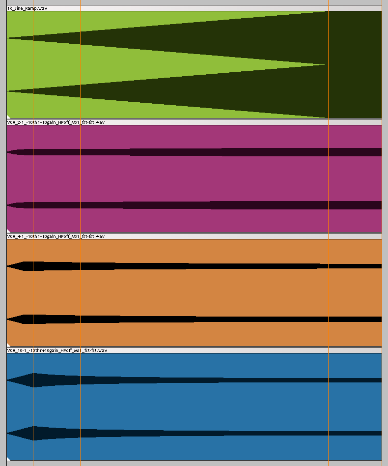
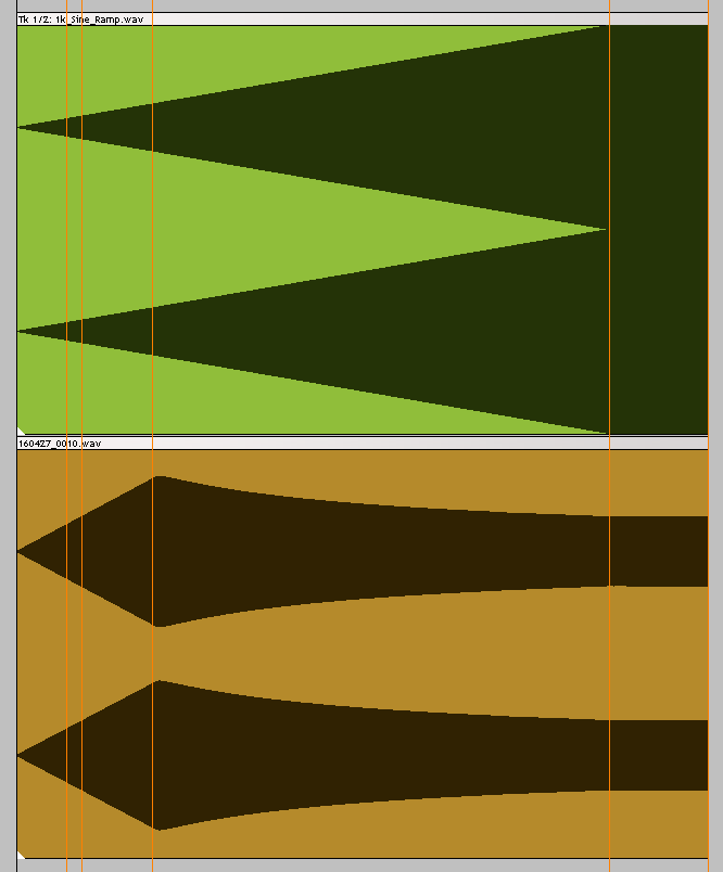
here is a comparison of the input and the output with 3 ratios:
VECA_ratios_001.png


top is the 1k sine ramp that goes out on the RME FF880, into the VECA
then 2:1, 4:1 and 10:1 down

Orange markers show -20, -18, and -12dBFS (4th is at 0dBFS) output.

the other settings: (set with static  -15dBFS 1k sine)
* Threshold : in 2:1 mode i turn the Threshold down (CCW) until RME input shows 10dB less signal coming in, so -25dBFS
* Attack : fast (fully CCW)
* Release : fast (fully CCW)
* HP SC : off (fully CCW)
* MS Balance : S (fully CCW)
* Gain : +10dB compensated
* Blend : off

i think what i have here is not a flawless build, right?.
ive built / populated another front controller PCB, and it works the same - so i think my problem is on the main PCB and/or my wiring.

anyone having ideas on this, please?
thank you

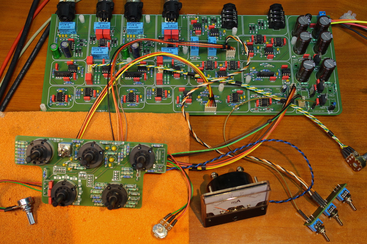
IMG_7532_vca.jpg

 
tata said:
sure my 1st VECA build sounds good, but now as i dive in a bit more i think id need help.

here is a comparison of the input and the output with 3 ratios:
VECA_ratios_001.png


top is the 1k sine ramp that goes out on the RME FF880, into the VECA
then 2:1, 4:1 and 10:1 down

Orange markers show -20, -18, and -12dBFS (4th is at 0dBFS) output.

the other settings: (set with static  -15dBFS 1k sine)
* Threshold : in 2:1 mode i turn the Threshold down (CCW) until RME input shows 10dB less signal coming in, so -25dBFS
* Attack : fast (fully CCW)
* Release : fast (fully CCW)
* HP SC : off (fully CCW)
* MS Balance : S (fully CCW)
* Gain : +10dB compensated
* Blend : off

i think what i have here is not a flawless build, right?.
ive built / populated another front controller PCB, and it works the same - so i think my problem is on the main PCB and/or my wiring.

anyone having ideas on this, please?
thank you

IMG_7532_vca.jpg

As always, I would love to try and help, but based on your post and collected data, I have to admit, I have absolutely no idea what you are doing, or what your problem is, so maybe you could write a sentences in the style of "I would expect X, but I am getting Y" to make it more clear!? Also share your reasoning!?

If I can even understand the problem (not something I can guarantee), it would also be nice to know what those wav files actually show (no ranges or resolutions given), and what you expect them to show.

Finally, dBFS is not a helpful scale of measurement, unless we know the calibration of your converters.

Gustav
 
thanks Gustav,

im trying to show the negative compression i get, its most visible on the 10:1 wav (blue)
the original / output 1k Sine ramps from -inf to 0dBFS in about 22 seconds, linear.

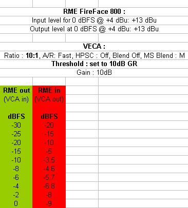
RME FF800 :
• Input level for 0 dBFS @ +4 dBu: +13 dBu
• Output level at 0 dBFS @ +4 dBu: +13 dBu

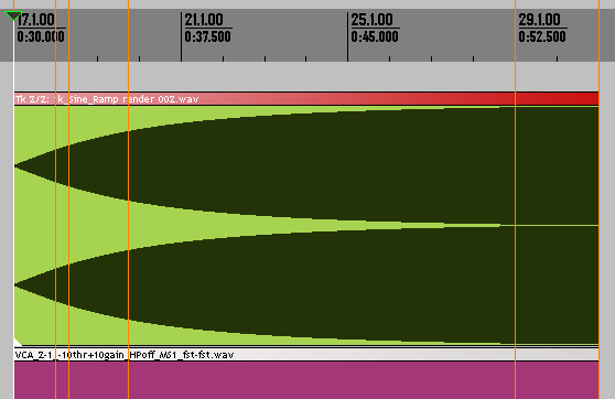
i'd expect something like this:
ITB_compress_001.png

(this is a random compressor plugin, threshold at -10dB, attack at 0.5ms, release: 100ms, 10:1 ratio, gain : +10dB)
 
tata said:
thanks Gustav,

im trying to show the negative compression i get, its most visible on the 10:1 wav (blue)
the original / output 1k Sine ramps from -inf to 0dBFS in about 22 seconds, linear.

RME FF800 :
• Input level for 0 dBFS @ +4 dBu: +13 dBu
• Output level at 0 dBFS @ +4 dBu: +13 dBu

i'd expect something like this:
ITB_compress_001.png

(this is a random compressor plugin, threshold at -10dB, attack at 0.5ms, release: 100ms, 10:1 ratio, gain : +10dB)

I still dont really understand to be honest, but there may be a few things at play here to start with, so shooting kind of blind.

Full S means, mostly, "difference" is being detected on the side chain.  Are you sending this sine to both channels?

Also, you going very hot to the comp if 0dBFS = 13dBU. Measuring just one channel, signal spills into the side chain at around 12dBU. You're even hotter if you are sending stereo.  I dont see anything that makes me think negative compression - you have 10dB of make-up gain on the signal, already +13dBU (x2, if youre sending it to stereo), coming back very hot as well (0dbFS on the input meter, calibrated to +13dB FS as well!!!?).
I suspect an error in method and/or levels rather than the build, so try to go softer on it and see what happens.

Gustav
 
yes, im sending the signal into both channles (you can see the stereo waveforms)

i understand that the signal gets hot as the sine ramps up to 0dBFS, but i shouldnt see what i see on the blue (also on the orange) - after the -20dBFS marker the VECA output signal going down as the input goes up. 

http://beatbybit.com/gears/1k_Sine_Ramp.zip  - if you could record this thru a properly built VECA, that would help me.
please set Threshold to approx mid. position, Gain to mid position too, 10:1, fast Attack/Release, MS : S, HP SC off, Blend off.

you should see a signal that only goes up, right? even if the input gets very hot towards the end of the sine sweep.

thank you.
 
Hi,
Honestly, I don't really understand how your tests should indicate  a flaw in your build. What I can see is, without knowing specific details of this build, that there are a few capacitors missing around the lorlin at the bottom left.
Bernd
 
thx Bernd,

those are the HF SC filter caps, they shouldnt make any difference at HP SC off position - but maybe im wrong.

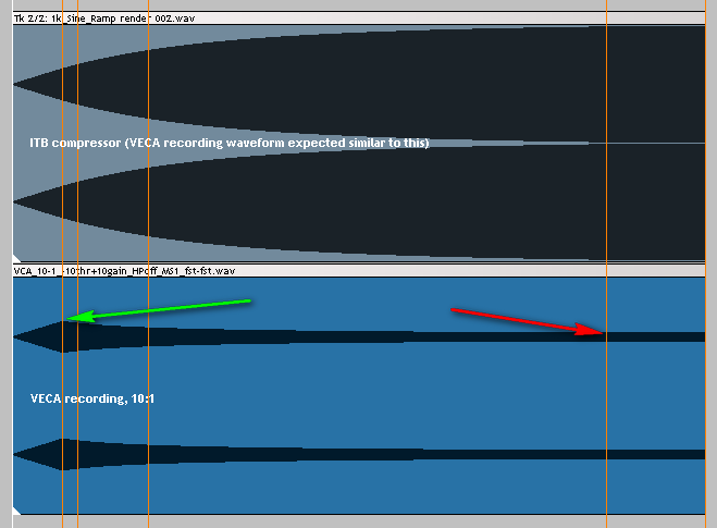
can you see the ramp up, then ramp down on the orange and blue .wavs? (4:10 and 10:1 settings) vs. the ITB compressor's waveform, which is constantly ramping up? (the green .wav in my later post)
 
I would stuff the caps anyway. I would also put aside your tests for a while and just feed it with some drums. Test various compression ratios, threshold setting, sc filtering and attack/release setting. Let your ear decide whether the unit works as it should. Then I would run a few tests with RMAA (audio analyser) and evaluate and compare the results, just to check that there isn't anything totally wrong. Then I would play with it for a few weeks and test further setting and other sources.
Cheers
Bernd
 
i hope this is easier to understand:

ITB_vs_VECA_001.png


can you see the red arrow showing a much quieter signal than the green? nevermind the output gain (VECA being quieter compared to the ITB render) just see the ramp going down while it should gently go up towards the end - as can be seen on the upper waveform.

Bernd,

i have another of that front panel PCB built, w/ F1-F7 populated. the behaviour is the same.
i do this test because i after some fun with real life tests, i started to hear the negative ratio (which is mentioned in other posts),
its not working as it should - my ears say. also i couldnt get the calibration values that others mentioned.
 
tata said:
i understand that the signal gets hot as the sine ramps up to 0dBFS, but i shouldnt see what i see on the blue (also on the orange) - after the -20dBFS marker the VECA output signal going down as the input goes up. 

Since you are running both channels , try running just one channel with the sine in your DAW to -16dbFS max, return to around -14dBFS max, see what happens.

I feel this trouble shooting consists more in finding out what you're trying to measure, what your interpretations are, and what your method is in doing so, rather than an issue with your build, but lets see where you are after trying what I suggested above.

Gustav


Gustav said:
Since you are running both channels , try running just one channel with the sine in your DAW to -16dbFS max, return to around -14dBFS max, see what happens.

Gustav

the upper waveform / output IS -16dBFS max, its set on the channel fader (waveform not updating)

VECA_Gustav_settings_001.png


sadly the GR meter doesnt move at all. (its a BP-670, 1mA meter w/ 2k resistor)
 
tata said:
Gustav said:
Since you are running both channels , try running just one channel with the sine in your DAW to -16dbFS max, return to around -14dBFS max, see what happens.

Gustav

the upper waveform / output IS -16dBFS max, its set on the channel fader (waveform not updating)

VECA_Gustav_settings_001.png


sadly the GR meter doesnt move at all. (its a BP-670, 1mA meter w/ 2k resistor)

The reason I asked you to try this was to see if you are butting heads with the levels  somewhere (converters/comp) in your initial test (just to rule that out). So, just try it again with a small upwards adjustment until you get some grab, see if you are getting more expected behaviour.

The meter should be calibrated if you are doing OCD type tweaking of the unit, just the 2K resistor will not make it spot-on.

I just ran the tone you uploaded through a channel getting compression, and getting attached result. Set-up is very crude, so can't do much with it in terms of accuracy, but you can see the return and the compressor grabbing, and I am not distorting it anywhere.

This is just a single channel, and for two channels, and if I try to wrap my head around it, I would not be surprised to see the sum of the identical sine to have  non linear effect on the feedback CV, which could very easily account for a slight increase in compression as the signal (summed) increases in amplitude. This will vary wildly with stereo content, level and relative to M/S setting, and lastly, it may not be hitting the 1:2 ratio exactly, but something just beneath (you can tweak this to perfection as well, as with every other parameter in almost any build).

There is no negative compression at play, (Part of my confusion was probably that you used that term).  I do not know why you are getting the "bump" a first", but this could simply be your somewhat extreme levels/setting playing a trick.

Try what Bernbrue suggested, running material through the comp and listening, and ease off your levels. I would guess theres nothing wrong with your build, and you are testing yourself into perceived problems.

Gustav
 

Attachments

  • Skærmbillede 2016-04-25 kl. 06.22.17.png
    Skærmbillede 2016-04-25 kl. 06.22.17.png
    23.8 KB
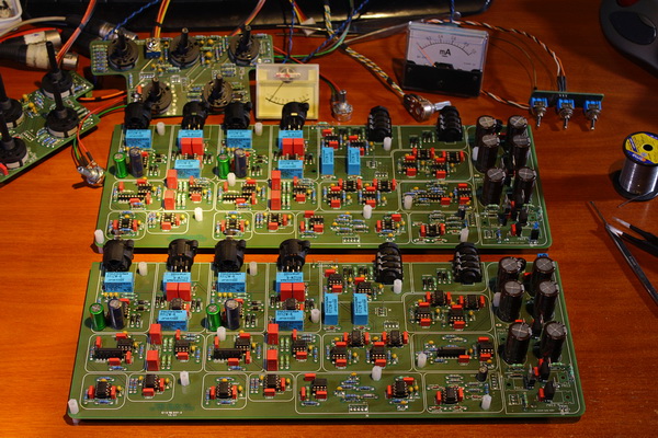
got the 2nd VECA built, (almost) all resistors are socketed..

IMG_7537_vca_2x_600.jpg


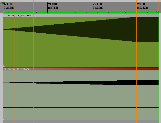
they both seem to work the same, here is the in/out comparison again:
(1k sine, 22sec long, -inf to 0dBFS ramp - top is the soundcard output / VECA input, bottom is what comes back from VECA, waveform is set to show 0dBFS at max)

VCA_b2_10-1_r001.png


this is the new build, at 10:1 Ratio, etc

VCA_b2_measure_001.png


i still think for a 22-second sweep, this doesn't seem right.  we should see a knee in the ramp, but even at 10:1 it should still trend upward. it might work well on percussive stuff but not so well on continuous signal, like vocals (as i experienced)

reason for this testing? i always love to see/hear how my gears work at the "extremes". because this hot input may happen anytime. (rockandroll, right? :) )
 
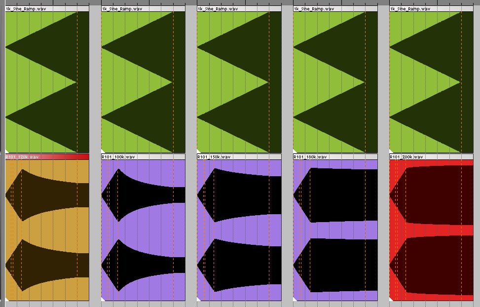
playing with R101, all settings left the same as in my previous post:

VECA_R101_variations_001.png


starting w/ 120k as marked on the PCB.
then 100k - gone more negative
150k : looks better
180k : even better
200k : bingo? it keeps ramping up, as expected. (the red item)

so far so good. i hope you now get what im looking for
 
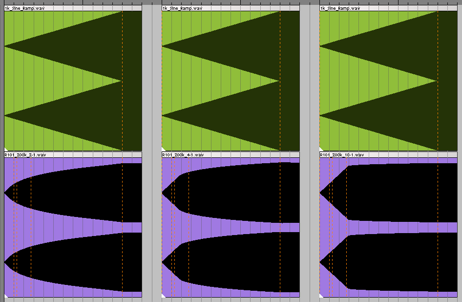
R101 : 200k  - checking Ratio :

R101_200k_Ratio_Test_001.png


2:1    -    4:1    -    10:1
looks perfect to me. im not sure it is technically perfect, but im happy so far.
and i honestly hope youre not bored with my posts.

now im back to testing more. lots of fun possible w/ all these "plug-n-play resistors" :)
 
It would be  great to add the errata if theres a resistor value to be upped here, but I will have to measure and make sense of it, since I can't wrap my head around your approach, how much you are compressing, if you are adjusting by read-out of an uncalibrated meter etc..

Ill check before end of the week (measured voltage in, measured voltage out, check the ratio, increase voltage in, check voltage out etc.), and if you've hit a discrepancy, well call it the rock n roll mod in your honour.

I at least have to make sure you are not just seeing double up on the CV and blowing on the old Aarhus/Oxford debate,  in which case,  your adjustment would have to go back as soon as you are no longer compressing stereo, ramped sine waves, and you have the benefit of the MS dial.

Until then. 

Gustav
 
Gustav,

i must say im havig soo much fun with this VECA now. the MS mode really makes a change, no more negative compression on vocal buss, i can hit it really hard - needle will break soon (dont care, its a cheap 1mA DC meter) - unless i change the resistor and call it a 40dB GR meter or so..

im happy that i have R101 socketed in the 1st build too - so it will be an easy "mod".
thanks for marking it on the PCB (and on the schemo)!
(the asterisk and MikeClev's post in the "SSL Clone compressor ratio measurements" thread was a big help.)

btw it seems i was wrong on the BOM / ceramic caps : 40.
stupid me, ive put a 100p ceramic in place of a 100n film on the 1st build (in the Ext SC block, where the block border is covering the bottom of the component label)
 
Back
Top