charge pump PS for tube voltages?

GroupDIY Audio Forum

Help Support GroupDIY Audio Forum:

This site may earn a commission from merchant affiliate links, including eBay, Amazon, and others.

Svart

Well-known member
Joined
Jun 4, 2004
Messages
5,134
Location
Atlanta GA USA
just an idea but, since i work in the realm of switching power supplies and power control, of what interest would a inverting(step up) power supply be to the tube guys? It's not hard to charge-pump 12v-120v to 100-300vdc at low current levels I know it would take some serious filtering but it still may be smaller/lighter/cheaper than standard power supplies.

any opinions?
 
I am interested. I have been dorking with low current charge pumps for mic capsule charging and ran into a few higher current DC-DC converters, but most of them used an esoteric transformer.
If you could design one that costs less than $35 and could give something like 25ma up to 300V, that would be great. how about a 50V tap for phantom power while you are at it? If it ran well above audio frequencies filtering would become easier.

Cheers,
Tamas
 
It's been done :wink:

http://www.paia.com/tubestuf.htm#siab

The PAiA-kit uses it, but iiric the unit I built years ago didn't reach it's expected voltage.
Note that this is starved plate stuff, but OK, that's only a matter of scaling the PSU.

Jakob has an article on his site as you'll know.

Bye & enjoy the upcoming days,

Peter
 
How about these supplies?

http://members.aol.com/sbench101/#Power

Best regards,

Mikkel C. Simonsen
 
good reading, some of the ideas with the CMOS driving I have used before, but for something like this it would be just as easy to PWM with a stand alone pwm IC, a FET driver and a MOSFET/IGBT along with the inductor/cap. lets say that the closest device would be a CCL inverter for an LCD panel. You could fine tune via the PWM, or make it completely adjustable.

just an idea, and if people are interested I would start on a fresh design. :thumb:
 
The PAiA-kit uses it, but iiric the unit I built years ago didn't reach it's expected voltage. Note that this is starved plate stuff, but OK, that's only a matter of scaling the PSU.

No, not really. CMOS gates run out of current around 2.5ma in this application so you will never get more than that. Most useful tube circuits will require a good bit more current.

Jakob has an article on his site as you'll know.

This is just the same CMOS gates only based stuff as the PAIA kit has.

We need something more than just gates, like a FET switch and an inductor (stores energy) to get more current. This one linked by Mikkel is pretty much it. http://members.aol.com/sbench101/PowerSupplies/lvps.gif
 
Why would you want a switching supply, phantom stuff?

If just to do it I understand

If line powered one can spec the right transformer.

Maybe for remote battery powered stuff. Sometimes even simpler supplys can cause problems with 60Hz sinewave driven supplys.

Some people still use valve diodes because of the more controlled turn on and off times

The phantom powered microphones all seem to use low plate voltage tubes and have a switcher for the heater. This seems to me to be more of a gimick.

A phantom powered device has limited energy. lets do a fast calculation 6.8k at 5ma is about 34V drop across each resistor leaving about 14 Volts for the circuit. I picked the numbers because phantom should supply 10ma IIRC so 5ma a leg.
 
As far as purpose goes, I was thinking along the lines of wall-wart operated tube gear like preamp and compressor with proper tube voltages. I cannot bear to hear or see starved plate tube gear. I don't know if Svart had microphones in mind at all. Anyhow, this is my angle.
 
Quote:
The PAiA-kit uses it, but iiric the unit I built years ago didn't reach it's expected voltage.
Note that this is starved plate stuff, but OK, that's only a matter of scaling the PSU.


No, not really. CMOS gates run out of current around 2.5ma in this application so you will never get more than that. Most useful tube circuits will require a good bit more current.

Putting a few more gates in parallel ?

Meant by 'scaling' that the PAiA-circuit needs a different voltage.
There must be something going on in my unit, since despite I built it according to plan I didn't measure the high voltage (OK, it's starved plate, let's use +MT... :wink: ) as noted in the schematic.
That unit is not really in use, so it'll likely be never debugged. Other stuff to do.

Quote:
Jakob has an article on his site as you'll know.


This is just the same CMOS gates only based stuff as the PAIA kit has.

Yep, the same idea.

But why not use the reverse power-TX method ? Probably not less worries, but different worries.
But it isn't smaller/lighter/cheaper like you were after.
 
EH sells a nice transformer for tube circuits that one can mount in a box and power by a wll transformer.
 
[quote author="clintrubber"]But why not use the reverse power-TX method ? Probably not less worries, but different worries.
But it isn't smaller/lighter/cheaper like you were after.[/quote]
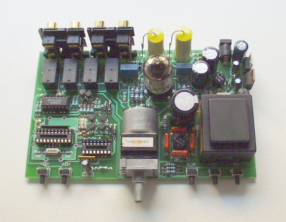
It can be both small and cheap though. Have a look at this small 12V wall-wart powered circuit:

RemTPre_small.jpg


Probably the smallest piece of tube equiment I have made so far (16*10cm).

Best regards,

Mikkel C. Simonsen
 
I was really only thinking that this would be interesting to attempt. The end project could be whatever you wanted to put it in and configurations could be varied due to specific needs.

so here are the criteria that i see as "law" when thinking about the design:

1. PWM is necessity. frequency based switching won't work because of the audio ramifications.
2. Cheap, easy to get parts. if we have to buy special inductors then why do it at all?
3. small size. If this PS is something that people want, then it's going to have to be as small as possible so that anyone could stick it in a mic if they felt like it, but by nature this will be small anyway.
4. simple design, easy to modify for your needs( :green: that's DIY right?).

and here are some considerations that might affect the design and need to be thought about:

1. To surface mount or not? I prefer it, others don't.
2. 2 sided PCB or not? I'd rather do it one sided, it cuts complexity and cost, but routing traces around parts might affect aspects of the device(noise, false triggering, slower FET responce due to gate capacitance, etc)
3. determine input voltage. since we aren't talking about building a whole dc-dc converter, lets set the input voltage and forget about the need to track and compensate.

any more opinions/comments? :thumb:
 
ok so looking at those schematic pages, this one: http://members.aol.com/sbench101/PowerSupplies/lvps250.gif has promise. we can replace the comparator with a PWM chip such as my favorite the UC3525( http://focus.ti.com/lit/ds/symlink/uc3525a.pdf ), and the totem pole arrangements with a single FET driver such as the TC427( http://ww1.microchip.com/downloads/en/DeviceDoc/21415b.pdf ) to a simple MOSFET with integral "flywheel" diode such at the IRF840. Or we could go one step further and get some of the new ones with a shottky flywheel diode for more efficiency.. however, i haven't had the chance to play with those yet so i don't know much about them..yet.

oh and it looks more like a flyback is more in tune with this design than a charge-pump. I think the caps/diodes needed to do that would be prohibitive anyway.
 

Latest posts

Back
Top