Chycki Tube DI grounding arrangement

GroupDIY Audio Forum

Help Support GroupDIY Audio Forum:

This site may earn a commission from merchant affiliate links, including eBay, Amazon, and others.

Mondy

Well-known member
Joined
Feb 11, 2012
Messages
60
Location
UK
Hi

I am looking at trying a build of the Chycki tube DI’s but whilst looking through the article here…

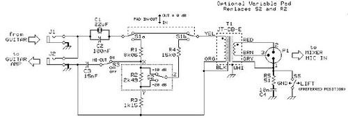
http://twin-x.com/groupdiy/albums/userpics/Buffered_Tube_DI_r.jpg
http://twin-x.com/groupdiy/albums/userpics/Buffered_Tube_DI_2_r.jpg

I am a little concerned about the grounding considering it has a built in mains power supply. The text reads…

There is no wall ground connected to the DI because any differential current between the box and components could induce hum by capacitance. The shield of either the input or balanced cable provides suitable protection and since the unit is never used without both cables intact, everything stays nice and safe.

Is there any way around this as I would rather have a permanent earth bond to the case for safety. Could the circuit 0V be isolated from the chassis by using insulated jacks and then only connected via the earth lift switch or similar or will this result in noise?

What is the consensus here on the board on the correct way to handle this?

Cheers
Ray
 
right away the transformer can give you ground isolation , he's not a E.E. , but
I've built a couple of those for friends with no problems
 
Thanks Greg

By the transformer do you mean the power transformer? if so what would happen should that fail to ground, unlikely, but not impossible?

Also, how do you find the ones you have build, do they perform, sound good?

Cheers
Ray
 
This is very dangerous. Mains enters the box and with nothing plugged into it the chassis could become live. You need to connect the mains safety earth to the metal box where it enters the box. As it stands I think it would be illegal in most countries.

Cheers

Ian
 
I agree totally Ian!

Would isolating the signal common from the case (Bo-Hansen DI style) be a suitable solution as I really would want a permanently bonded mains earth on the enclosure?

Ray
 
Mondy said:
I agree totally Ian!

Would isolating the signal common from the case (Bo-Hansen DI style) be a suitable solution as I really would want a permanently bonded mains earth on the enclosure?

Ray

A DI box is in the unfortunate position of having unbalanced inputs and balanced outputs. The problem with unbalanced inputs is you don't know what happens to the ground connections at the other end.. If you tie them to safety ground at your end then you know that even if there is a fault in the equipment the unbalanced inputs are connected to, you will remain safe but you might get a ground loop through a common safety earth connection. If you lift the 0V signal from the case your electronics will float up to the ground potential of whatever the unbalanced inputs are connected to. This may or may not be healthy for your electronics. It will certainly eliminate potential ground loops. If you do this then tre should be no need for the ground lift switch.

Cheers

Ian
 
Hi Ian

I am thinking maybe Bo's DI ground lift scheme could be one way then.  The DI is intended solely for guitar pickup work, mainly live, but also studio if quiet enough. How would you go about it?

Cheers
Ray
 
I was thinking the same thing as Ian.  Unlike Bo's DI, this isn't phantom powered.  So pin 1 can go to chassis and the input jacks can have their shields tied to chassis as well. 

The power supply secondary can all be tied to "B-" (X on the schematic), without the chassis to B- connection (the one right where the "X" label is on the schematic).  The the circuit ground can be isolated from the chassis and there should be no coupling to taint the audio paths should any chassis currents be flowing.

It seems incredibly irresponsible to recommend not bonding safety earth on a mains powered box, all for "hum reasons".  I mean, how much are you going to be bothered by hum once you are 6 ft. under?  :eek:
 
Thanks Matador

I think I've got it, its just when you say...

So pin 1 can go to chassis and the input jacks can have their shields tied to chassis as well.

That makes sense to me, then you say...

The the circuit ground can be isolated from the chassis and there should be no coupling to taint the audio paths should any chassis currents be flowing.

But how can the circuit ground be isolated from the chassis if the input jacks have their shields tied to the chassis, aren't the input jack shields (sleeves) and circuit ground the same?

Cheers
Ray


Mondy said:
Thanks Matador

I think I've got it, its just when you say...

So pin 1 can go to chassis and the input jacks can have their shields tied to chassis as well.

That makes sense to me, then you say...

The the circuit ground can be isolated from the chassis and there should be no coupling to taint the audio paths should any chassis currents be flowing.

But how can the circuit ground be isolated from the chassis if the input jacks have their shields tied to the chassis, aren't the input jack shields (sleeves) and circuit ground the same?

Cheers
Ray

Yo are right. The problem is the input/output jacks are connected to 0V and to the chassis so if you are going to lift 0V from the chassis you have mount the jacks on insulators.

Cheers

Ian
 
Mondy said:
I am a little concerned about the grounding considering it has a built in mains power supply.
All what the others said...
However, you have the possiblity of using a special isolation transformer, as in medical applications. The cost of that transformer may force you to sell a kidney, though. 
 
abbey road d enfer said:
Mondy said:
I am a little concerned about the grounding considering it has a built in mains power supply.
All what the others said...
However, you have the possiblity of using a special isolation transformer, as in medical applications. The cost of that transformer may force you to sell a kidney, though.

If he implements the original design, then circumstances might leave him with two kidneys to spare!  ;D
 
Ray,

My ground loop suppressors, unfortunately, can not help you with electrical safety in this case.

It is intended to prevent ground loops and still be able to transfer a good 0 volts/ground for the phantom powering, without having to find their way to the DI-box via the studio's safety grounding systems in electrical outlets.

In your case, a polyester 0.1uF/160 (or more) ac volt capacitor in series with XLR pin-1 will be satisfactory for securing electrical safety from the DI-box to the mixing console.
This works well because this signal is transformer balanced, and use the screen as an interference canceller.
It usually works well to connect the screen with a capacitor to separate it from the chassis ground, but still ensure that buzz and RF/HF interference think the screen is connected to ground.

What I see as a more dangerous problem is that your DI-box will be grounded to the electric guitar/bass in the same chassis and electronics which also mains transformer is connected.

I have never liked embedded mains transformer in small compact crowded built effects pedals,  especially here in Europe where we have 230 volt mains voltage.
If an accident should occur with short-circuit. the guitarist get mains voltage right through his body as he holds the guitar and maybe while'll sing into a microphone with the lips on mike grill/metal ball.

Instead, I would suggest a different solution to the security problem.

A good way is to split the mains transformer in two separate parts.

One part is a 120 to 12 volt plug-in AC adapter outside DI box.
The second part a little backwards connected mains transformer 12-120 volts mounted inside the DI-box.

(you can, of course use 6 volt transformers as well, but I think there is more choice of 12 volts ac adapters,  it is easy to connect the tube for 12,6 volts filament, and adjusted with R10 for right dc voltage)

In this case, the rectifier for the tube filament, takes 12 (6) volts ac between transformers, i.e. ac input to the DI-box mains transformer.

If these transformers are of good kvaliét everything will work fine, and DI box will now be pretty electric safe.

--Bo
 
Thanks for your help Bo, it’s very much appreciated!

Would your idea of a capacitor connection of pin 1 to the chassis also be supplemented by a 50 – 100ohm resistor in series with the cap. This is as per the lift switch in the classic Jensen JT-DB-E passive direct box schematic, would I be able to use this scheme on the Tube DI, or would an earth lift just not be possible?

Thanks also for your smart idea of double isolation and I will keep this idea in mind. I do not see this as being too much of an issue as surely mains transformers are incorporated in practically all tube guitar amps for example and as long as the chassis is permanently bonded to the incoming mains safety earth and cannot be “lifted”, and correct and suitable fusing is used, this should be sufficient.

I know there are risks when different system earths are used for say backline power and front of the house console in for example a festival setup or similar, but this tube DI would solely be for personal setups as I always take my trusted solid state P48 active DI for larger concerts where I do not know the setup and therefore never get involved in any backline power schemes.

I plan to incorporate the mains transformer and this will be a toroidal transformer with a primary to secondary foil screen which will also be bonded to same earth point on the chassis as the mains input earth. It is just the earth loop, ground lift, pin 1, noise side that I sometimes struggle to get my head around as there seems to be almost too much information on the interweb regarding this and I want to be sure that I have the wiring scheme essentially “right” in this regard!

Cheers

Ray


Hi Abbey Rd

Yes I thought parallel is the usual as this should prevent the circuit 0V floating up in potential as Ian mentioned earlier. But it shows it in series in the Jensen DI schem here...

327088588_501e3f73cd.jpg


Any ideas?

Cheers
Ray

 
Mondy said:
Yes I thought parallel is the usual as this should prevent the circuit 0V floating up in potential as Ian mentioned earlier. But it shows it in series in the Jensen DI schem here...
It looks like this one has been designed by the marketing department. The bipolar 22uF at the input with a 0.1 in parallels comes directly from the Audiophool collection book "How to become an audio designer in a week-end". I guess Bill Whitlock has never approved this "design".
 
Ah yes I see your point  ;D

The pdf does recommend gold plated connections as well so you could be onto something there! Mind you I bet there are a fair few DI's out there built from this schematic, if I had a need for a passive box, I would have been one as well!

I was wondering if I could use the same grounding scheme (with the lift resistor 100R and in parallel with the cap!) for the Tube DI?

Cheers
Ray
 
Mondy said:
I was wondering if I could use the same grounding scheme (with the lift resistor 100R and in parallel with the cap!) for the Tube DI?
You could certainly, although in the course of your modus operandi, a ground lift may not be useful at all. It is useful to break ground loops that seldom fail to appear when there's an amp in conjunction with a DI.
 

Latest posts

Back
Top