Current Meter Monitoring of Power Amp Output.

GroupDIY Audio Forum

Help Support GroupDIY Audio Forum:

This site may earn a commission from merchant affiliate links, including eBay, Amazon, and others.
@moamps ...... In a cutting system, a limiter is often in the signal chain. It's a tangled web, however, because of:

1. The RIAA pre-emphasis that greatly boosts the high frequency content coming from the cutting amp.

2. The amplifier driving the cutting head typically provides 100+ Watts RMS into a device you can hold in the palm of your hand. The head is usually fed with Helium gas in order to keep the "guts" cooled.

Bri
 
It doesn't matter what the output power is, if we define a maximum current of 2A. Furthermore, a closed loop is proposed here, where the control signal is not the voltage, but the current. This is better in a way because the impedance of the cutting head is certainly not linear and independent of frequency.
 
That 2 amps is an average power. With an 8-ohm-ish head that is 32 Watts. Instantaneous peaks can be up to the clipping level of the amplifier. That's how cutting systems work....always on the edge <g>>

Bri
 
In the end, that signal could be used as a sidechain for a limiter that would limit the maximum current of the output amplifier to the desired value (closed loop). This signal could also be displayed on a PC-based display with a spectrum analyzer and display of currents in, say, 1/3 octave frequency bands.
That is exactly what happens in the Neumann VG66. The sidechain signal for the HK66 High Frequency Limiters is taken from this current sense.
 
That 2 amps is an average power. With an 8-ohm-ish head that is 32 Watts. Instantaneous peaks can be up to the clipping level of the amplifier. That's how cutting systems work....always on the edge <g>>

Bri
The Neumann SX74 can take 7 joules. It can’t take more than about 5W RMS. 2A is when the head blows up.
 
A ground-referred current shunt monitor is relatively easy to implement.
As others have suggested place a low-value series resistor in the ground return for each channel.
This makes the current measurement ground-referred and doesn't require a floating connection.
The lower the shunt value the less invasive it is. (<0.1Ω)
Connect a differential amplifier with gain - a THAT 151X is the quickest and easiest requiring only one resistor. Easily done with an op amp as well.
Using a diff amp sensing directly across the resistor legs provides a Kelvin connection. For simplicity you could use a single-ended AC amplifier.
Scale it for say 1V/Peak Amp. With 0.1Ω at 2A you'll need a gain of 10 to get 2V full scale.
Connect the output of the differential amp to a peak-responding audio bargraph meter available on eBay or Amazon or my GR20.

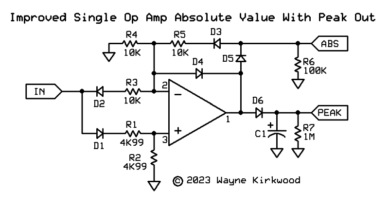
If you want to roll your own absolute value (bipolar) peak detector this one is super-simple using only a single op amp.

Improved_Single_Op_Amp_Absolute_Value_With_Peak.jpg


https://proaudiodesignforum.com/forum/php/viewtopic.php?p=17356#p17356

The above is modified from Spani, 1969. D3 compensates for the Vf of D1 and D2. D5 compensates for the Vf of D6.
 
Last edited:
A ground-referred current shunt monitor is relatively easy to implement.
As others have suggested place a low-value series resistor in the ground return for each channel.
This makes the current measurement ground-referred and doesn't require a floating connection.
The lower the shunt value the less invasive it is. (<0.1Ω)
Connect a differential amplifier with gain - a THAT 151X is the quickest and easiest requiring only one resistor. Easily done with an op amp as well.
Using a diff amp sensing directly across the resistor legs provides a Kelvin connection. For simplicity you could use a single-ended AC amplifier.
Scale it for say 1V/Peak Amp. With 0.1Ω at 2A you'll need a gain of 10 to get 2V full scale.
Connect the output of the differential amp to a peak-responding audio bargraph meter available on eBay or Amazon or my GR20.

If you want to roll your own absolute value (bipolar) peak detector this one is super-simple using only a single op amp.

Improved_Single_Op_Amp_Absolute_Value_With_Peak.jpg


https://proaudiodesignforum.com/forum/php/viewtopic.php?p=17356#p17356

The above is modified from Spani, 1969. D3 compensates for the Vf of D1 and D2. D5 compensates for the Vf of D6.
I already suggested the small value resistor in the ground line in my post #5 in this thread. This is also called a Kelvin connection.
===
While those extra diodes may compensate for forward drops due to D1 and D2 with large signal swings, my early morning analysis suggests a whopping dead band for audio signals less than conduction for D1 and D2. Maybe it will make more sense to me later.

JR
 
I already suggested the small value resistor in the ground line in my post #5 in this thread. This is also called a Kelvin connection.
===
While those extra diodes may compensate for forward drops due to D1 and D2 with large signal swings, my early morning analysis suggests a whopping dead band for audio signals less than conduction for D1 and D2. Maybe it will make more sense to me later.
I did mention Lord Kelvin's name. Your original suggestion didn't mention anything about a 4 wire connection. If the sense resistor is at the ground binding post of the power amp a three wire connection might be good enough but if the sense resistor is near the cutter head with I*R drop in the ground lead a true "four wire" Kelvin connection will be more accurate.

I built that peak detector and as I mention elsewhere it's linearity falls off below about 250 mV. It's somewhat usable below that as linearity falls off but since we're using it for an overload indication at 2V peak or greater the benefit of it's simplicity may outweigh something more complicated.

Y'all have fun...
 
There are many examples of precision rectifiers that don't suffer from low level errors. Op amps and diodes are relatively cheap.
===
There are multiple ways to skin this cat.

Good luck.

JR
 
A 'normal' VU meter reads zero VU at 1.228 Volts and a proper meter to full spec can be very flat 'response. The Sifam AL29? VU meter reads 0VU from around 20 Hz to around 100KHz and only uses a 3K6 resistor (apart from the diodes that are inside the metyer movement casing.
I have measured the Sifams several times and surprised how good they are for only springs and magnet. The response below 20Hz is difficult to see because you have to average by eye, certainly at 10Hz! Of course you are searching a CURRENT meter so rearrangement perhaps with a low value series resistance and an op amp stage to 'convert current to volts.
 
There are many examples of precision rectifiers that don't suffer from low level errors. Op amps and diodes are relatively cheap.
===
There are multiple ways to skin this cat.

Good luck.

JR
Wiring up extra diodes and op amps for a one-off on Veroboard wouldn't be cheap if I were billing it.

Since the error occurs around the bottom dot on a 20 step meter where the concern is the top dot I think you're over-engineering.

Next time I simply won't contribute here. I try not to already and when I do I usually regret it. Same for DIYAudio. Everything turns into a pissing match for people who just are trying to be helpful. "F" that.
 
Next time I simply won't contribute here. I try not to already and when I do I usually regret it. Same for DIYAudio. Everything turns into a pissing match for people who just are trying to be helpful. "F" that.

Unfortunately, it seems that way to me too.. Things are evolving, maybe not in the direction some of us want..
 
Here is the SI66 Circuit Breaker from the VG66 amplifier rack. It looks like the use transformer isolation into a bridge rectifier into a DC current meter.

The cutterhead drive coil sits in the bridge in the upper part if the first page.
 

Attachments

  • Neumann_SI66_CircuitBreaker-1_20200711_0001.pdf
    301.4 KB · Views: 1
  • Neumann_SI66_CircuitBreaker-2_20200711_0001 2.pdf
    286.8 KB · Views: 0
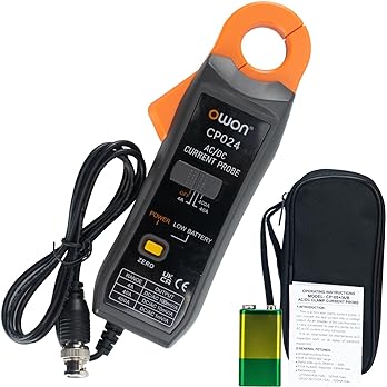
It may be expensive to get a good wide bandwidth current probe (current clamp).
===
I have never used one in a product. I messed around with a cheap one, to detect when my sump pump down in my crawl space was finished draining water and pulling air. I never finished trying to make this work since I got an old school float switch working. FWIW the cheap current probes I messed with are only 50/60Hz which was all I needed for my sump pump, but you will need something more expensive.

This puppy for $180 claims -3dB @ 200kHz https://www.amazon.com/OWON-Oscillo...sprefix=wideband+current+probe,aps,120&sr=8-4


71miD3z-A4L._AC_UL348_SR348,348_.jpg
but not obviously a good format for your application.

JR
 
Last edited:
An oscilloscope current probe would be my first choice. Regardless, here is a useful article on current measurements.
https://www.digikey.com/en/articles/understanding-selecting-effectively-using-current-probes
Keep in mind that the current measurement is a "full time" requirement in this application. IOW, a panel in the cutting amp setup holds a pair of meters that do just that one task any time a lacquer is being cut.

Bri

/EDIT: That Digikey article does provide a great discussion of the methods.
 
Interesting, the circuit breaker in the Neumann SAL74 (SEL74 B) does things a little differently, same basic idea but it uses a small DC offset to excite the bridge and has temperature, peak current and a average current with multiple time constants driving the trip circuit (There is also logic to inhibit trip reset if signal is present.

One interesting aspect of the design is that the whole circuit floats on the bridge output using an isolated winding on its power transformer, and is designed such that the bridge coming into balance corresponds to 200 degrees c at the cutting head coil and a trip, this makes the high set point independent of the DC offset setting on the amp (Which sets the 25c end of the scale).

The temperature bridge is somewhat slow responding (47K, 10uF), so about 0.5 seconds TC, but does modulate the current limit which while not right makes it effective in most cases.

A modern one would probably take the bridge voltage and the current measurement into a small micro to compute I^2 and work the over current limits based on that.

It is worth noting that the Bridge resistor and 2.2uF film cap serve to partially tune out the cutter head inductance at high frequency reducing the required voltage from the power amp somewhat. Cutters need nearly no power at low frequency, the action all happens in the top octave or so. The extensive motional feedback used in these systems flattens the response including the an anomalies caused by this network.

The HF limiter in that set of electronics does not take feedback from the current, instead applying a mess of LC filtering to the modulation to control the HF limiter. Somewhat more surprisingly the velocity threshold is fixed, I would have expected this to vary with cutting diameter and speed selection, guess making that available was felt to be unnecessary?
 

Attachments

  • Capture.PNG
    Capture.PNG
    740.6 KB · Views: 0

Latest posts

Back
Top