[silent:arts]
Well-known member
THE PSUs
as mentioned before the PCB contains 3 PSUs:

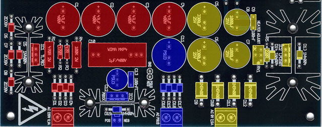
all components colored red are part of the
High Voltage PSU
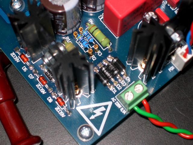
CAUTION: Mains or High Voltages are lethal, you have to work very carefully here.
it is a good idea to always have a separate Voltmeter constantly connected to the High Voltage when working, this can be easily done at R128 or R218.
since this is an adaption of the Gyraf G9 High Voltage PSU, please read the Basic safety rules Jakob wrote on the Gyraf G9 site.
R2 & R3 are setting the B+ voltage, I used some sockets on my prototype to empirically find the "right" values:

with 470R + 47R resistors (silkscreened values) I get 238V after Rx28, close enough.
if you want to come closer to the 243V from analags schematic you can use a single 510R and a jumper, this gives me 241V (again, after Rx28).
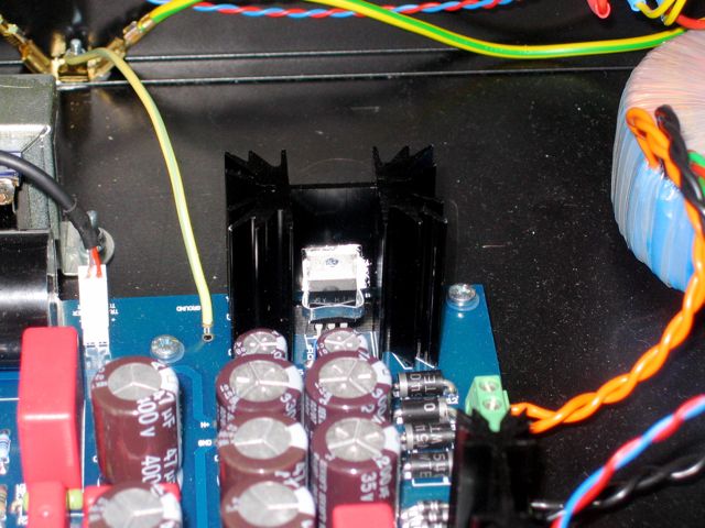
don't forget to mount the TL783 insulated to the heat-sink, otherwise you will have a short from the regulator's output to ground !!!
!!! be aware that this PSU needs a load to work properly, with no tubes inserted you will have more than 350V !!!
!!! with no tubes inserted the High Voltage caps need a very long time to discharge, read the safety rules again !!!
if you are unsure and afraid of the tubes, test with only one channel fitted first.
and yes, you need a power transformer with a 220V - 250V secondary @ 0.1A even living in a 230V country.
DON'T KILL YOURSELF
all components colored yellow are part of the
Heater PSU
the power transformer needs to have a 9V - 12V secondary @ 2.5A, and the LM350T gets hot.
you need a good heat-sink here !!! the SK129 38.1 I used in mine (and which is silkscreened on the PCB) is not enough in my opinion.

may be a SK129 50,8 or SK129 63,5 will work, but I don't have one of either to test.
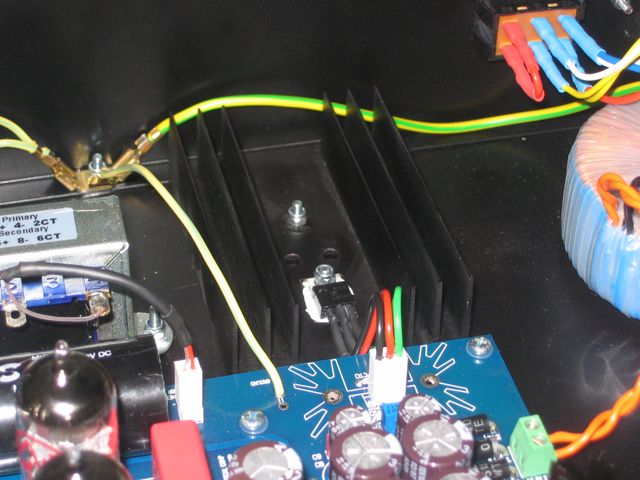
with a larger heat-sink and the regulator mounted off board to the chassis the regulator stays quite cool:

like the TL783, the LM350T must be mounted insulated to the heat-sink, otherwise you will have a short from the regulator's output to ground !!!
before inserting the tubes adjust the heater voltage to 6,3V using RV1.
there are two test points next to C8.
after inserting the tubes check again and readjust.
all components colored blue are part of the
universal PSU
use this PSU for relay bypass, meter lamps, VU buffers, what you want.
if you don't plan to use any of the above you can just let this components out.
the output voltage is chosen by the 78XX you use.
take 7805 if you want 5V, 7812 for 12V, 7824 for 24V.
of course you need a matching secondary on your power transformer, and C11, C12 and C13 should be in the right voltage range.
if you want a real true hardwire bypass take very low values for C11 and C12.
at the moment my PSU3 holds the power for 4 seconds after switching off the unit, using 2200uF and 100uF (24V).
will have to change this since I want the compressor to be immediately in bypass after switching it off.
it is not necessary to insulate the 78XX from the heat-sink, but more elegant.
the PSU3 has its own ground path, you can use it floating, or use a little jumper (provided on the PCB) to connect the PSU3 ground to the main PCB ground.
hope this is helpful,
more to come
as mentioned before the PCB contains 3 PSUs:

all components colored red are part of the
High Voltage PSU
CAUTION: Mains or High Voltages are lethal, you have to work very carefully here.
it is a good idea to always have a separate Voltmeter constantly connected to the High Voltage when working, this can be easily done at R128 or R218.
since this is an adaption of the Gyraf G9 High Voltage PSU, please read the Basic safety rules Jakob wrote on the Gyraf G9 site.
R2 & R3 are setting the B+ voltage, I used some sockets on my prototype to empirically find the "right" values:

with 470R + 47R resistors (silkscreened values) I get 238V after Rx28, close enough.
if you want to come closer to the 243V from analags schematic you can use a single 510R and a jumper, this gives me 241V (again, after Rx28).
don't forget to mount the TL783 insulated to the heat-sink, otherwise you will have a short from the regulator's output to ground !!!
!!! be aware that this PSU needs a load to work properly, with no tubes inserted you will have more than 350V !!!
!!! with no tubes inserted the High Voltage caps need a very long time to discharge, read the safety rules again !!!
if you are unsure and afraid of the tubes, test with only one channel fitted first.
and yes, you need a power transformer with a 220V - 250V secondary @ 0.1A even living in a 230V country.
DON'T KILL YOURSELF
all components colored yellow are part of the
Heater PSU
the power transformer needs to have a 9V - 12V secondary @ 2.5A, and the LM350T gets hot.
you need a good heat-sink here !!! the SK129 38.1 I used in mine (and which is silkscreened on the PCB) is not enough in my opinion.

may be a SK129 50,8 or SK129 63,5 will work, but I don't have one of either to test.
with a larger heat-sink and the regulator mounted off board to the chassis the regulator stays quite cool:

like the TL783, the LM350T must be mounted insulated to the heat-sink, otherwise you will have a short from the regulator's output to ground !!!
before inserting the tubes adjust the heater voltage to 6,3V using RV1.
there are two test points next to C8.
after inserting the tubes check again and readjust.
all components colored blue are part of the
universal PSU
use this PSU for relay bypass, meter lamps, VU buffers, what you want.
if you don't plan to use any of the above you can just let this components out.
the output voltage is chosen by the 78XX you use.
take 7805 if you want 5V, 7812 for 12V, 7824 for 24V.
of course you need a matching secondary on your power transformer, and C11, C12 and C13 should be in the right voltage range.
if you want a real true hardwire bypass take very low values for C11 and C12.
at the moment my PSU3 holds the power for 4 seconds after switching off the unit, using 2200uF and 100uF (24V).
will have to change this since I want the compressor to be immediately in bypass after switching it off.
it is not necessary to insulate the 78XX from the heat-sink, but more elegant.
the PSU3 has its own ground path, you can use it floating, or use a little jumper (provided on the PCB) to connect the PSU3 ground to the main PCB ground.
hope this is helpful,
more to come


