D-AOC PCBs - the building and help Thread

GroupDIY Audio Forum

Help Support GroupDIY Audio Forum:

This site may earn a commission from merchant affiliate links, including eBay, Amazon, and others.
Hey thanks, that makes a whole lot more sense - I wasn't 'seeing' a threshold.

I'll label mine up as compression.

So I agree about the kick in point...unles you have an analogue stage out there in front, it will make it very hard to kick in coming out of a nominal digital system.

-T
 
Just getting parts together for this and have a question.
The output caps 10uf 600v Poly's , any other recommendations as I'm finding
them hard to get and VERY expensive , like £8 each !
Found nice ones at Farnell but they are axial and 7cm across, so perhaps too big ??

VTL5C4/2 can be had from smallbear for $6 each BTW

Any info on the size and "hole width" of the two smaller heat sinks ??
There's several dozen similar things on Farnell's site.

For the BIG one, I'm going to use a large 8x6cm heat sink and attach it to
the case bottom/back.

Marty.
 
[quote author="MartyMart"]Just getting parts together for this and have a question.
The output caps 10uf 600v Poly's , any other recommendations as I'm finding
them hard to get and VERY expensive , like £8 each !
Found nice ones at Farnell but they are axial and 7cm across, so perhaps too big ??
Marty.[/quote]

Marty,
spacing of the 10uF 630V Poly is 55mm. For the heatsink there is an ordering number in the BOM, look for further details there, pls. I´m just about to go on holiday. See you in three weeks.
Cheers
Bernd
 
Here you go :)
!PR32.jpg

regards
Bernd
 
Thanks Bernd, much appreciated :)

Enjoy your break .

Marty.

UPDATE __ UPDATE __ UPDATE !!

Here's the Farnell code for the 50mm high version : 1219493
and the 38mm high version is : 1219491
Footprint and board mounting are exact on these.

There should be plenty of room for the 50mm high, and it will dissipate more heat.
 
[quote author="living sounds"]I third this. If levels have to be this high it won't be much use as an insert in a digital system without plugging in a line amp in front of it...[/quote]

Good point. Any constructive solutions?
Maarten
 
well i like the lowering r103 idea that could work, but call me crazy but looking at the compression curves with the mods it looks like the blue led (parallel) it looks like a slightly steeper version of no mods, but the 100k across looks less steep, so......maybe if we just strap them both across we will get a similar slope with lower threshold, i think im going to try this when ever i get mine up, but if someone whos already got one wants to try i would be grateful, thanks
 
What if a 12AT7 or 12AX7 were used in place of V102? This would allow the gain-staging in the signal path to remain the same, but would allow for more gain in the side-chain. If the problem is only that there is too high a threshold, wouldn't a higher amplification factor in the opto driving circuit effectively lower the threshold?
 
Sure, try a 12dw7 & 5751 there as well.

Anyone working on a sidechain HP? Would a capacitor in series with R110 work? How about one parallel to R112.
 
Just a few quickies,

would any body able to tell me if this project can drive my 1ma VU meters??

And was the EDCOR 10k/10k good on the input?

Best
Pete
 
[quote author="OneRoomStudios"]What if a 12AT7 or 12AX7 were used in place of V102? This would allow the gain-staging in the signal path to remain the same, but would allow for more gain in the side-chain.[/quote]
this would be the right way to lower the threshold for sure.
but without changing some component values around the tube there won't be any difference.

a little input transformer test will follow within the next two days.

btw, this is an open project, feel free to do your own experiments :thumb:
 
thanks volker, well def try my OEP's too, the EDCORs are just incredible value for money, cant quite believe how cheap they are..I think i read Analag use's them all the time..
 
INPUT TRANSFORMERS

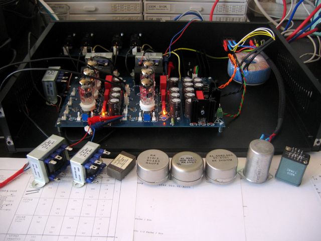
today I opened up my box of transformers, and took some of them out where I thought they could fit in this circuit.

IMG_4889.jpg


from left to right:
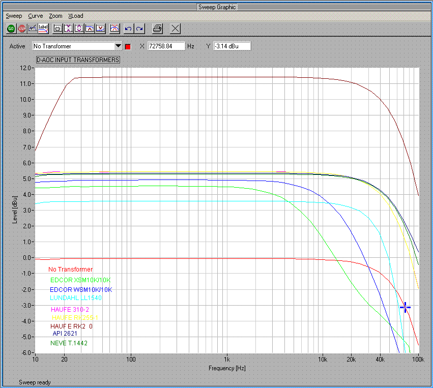
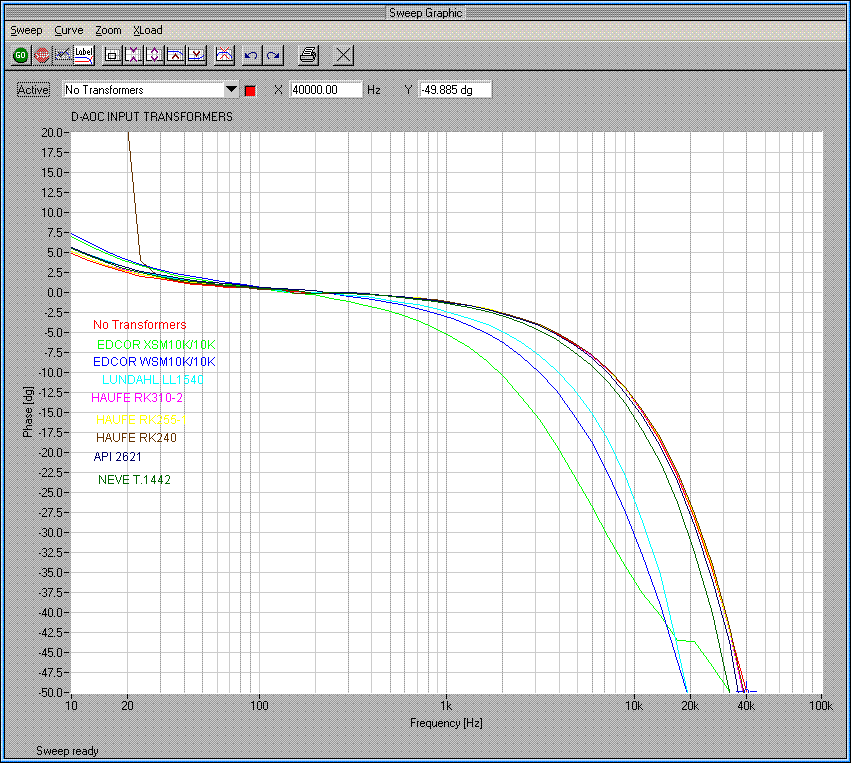
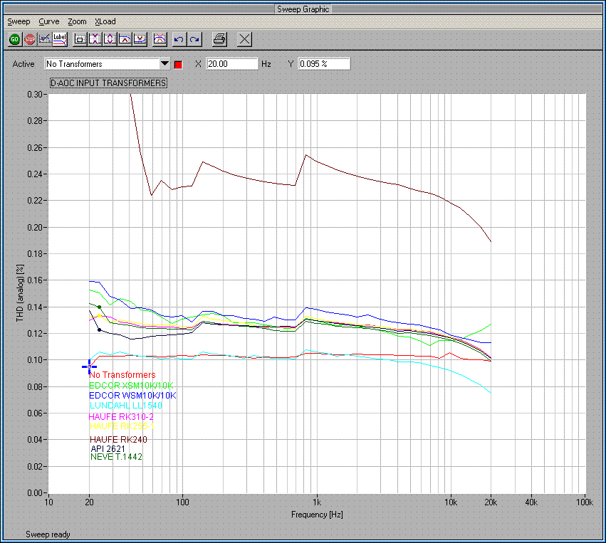
Edcor XSM10K/10K, Edcor WSM10K/10K, Lundahl LL1540, Haufe RK310-2, Haufe RK255-1, Haufe RK240, API 2621, Neve T.1442 (= 31267)

this was not a listening test :green:

FREQUENCY RESPONSE:
DAOC-InputTransformersFreq.GIF


PHASE SHIFT:
DAOC-InputTransformersPhase.GIF


THD+N:
DAOC-InputTransformersTHD+N.GIF


Measuring conditions:
no output transformer,
Output Potentiometer = 100%, Input Potentiometer set for unity gain without transformers.
Generator Level = 0dBu
Zout 15Ω, Zin 100K
no Zobel networks etc used, just the transformers
(all at 1:1, except Haufe RK240 which is 1:2)
 
wow, there you have it.
losses from big iron/thick laminations, high dc-resistances (did you wire the ll1540 in series?) and the hf-characteristics from the different winding schemes.
many thanks for this test!
which hardware/software did you use?

-max
 
[quote author="MikoKensington"]When do we get to read about the subjective listening tests? :wink:[/quote]
from me ? never. too subjective :green:

[quote author="ioaudio"](did you wire the ll1540 in series?)[/quote]
yes

[quote author="ioaudio"]which hardware/software did you use?[/quote]
as always: Neutrik A2 / AS04 (which is a pain. NTI - please, do an update for this software) :roll:
 

Latest posts

Back
Top