D-EF47 Tribute To Oliver Archut U47 Build Thread.

GroupDIY Audio Forum

Help Support GroupDIY Audio Forum:

This site may earn a commission from merchant affiliate links, including eBay, Amazon, and others.
Hi Dan,
I've been fascinated with the use of relays for onboard switching. I was studying your schematic and I went ahead and drew a version up that seemed more like a traditional schematic rather than a board layout document.

I'd be happy to send you a pdf that you can share with everyone, but I'm not sure that the diode near the reed switch is placed correctly and I would appreciate it if someone else can check for errors etc.

Can you explain where I should put the diode?

Thank You.
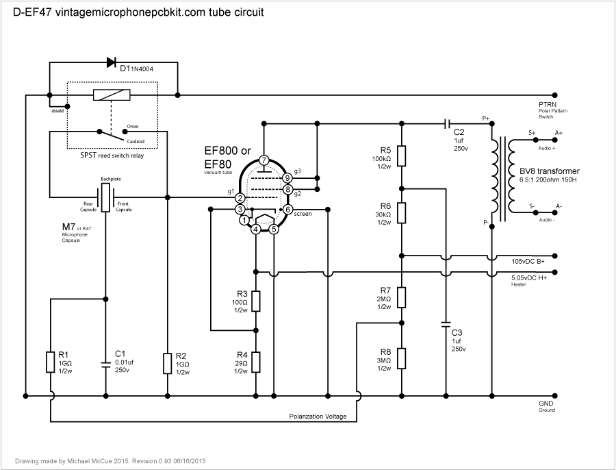
D-EF47-EF800.jpg

 
trans4funks1 said:
Hi Dan,
I've been fascinated with the use of relays for onboard switching. I was studying your schematic and I went ahead and drew a version up that seemed more like a traditional schematic rather than a board layout document.

I'd be happy to send you a pdf that you can share with everyone, but I'm not sure that the diode near the reed switch is placed correctly and I would appreciate it if someone else can check for errors etc.

Can you explain where I should put the diode?

Thank You.

D-EF47-EF800.jpg

Michael I love your work and schematic, yes I would be pleased to have sent it down to me via my email so I can post it and share it  , at the meantime I will be checking it out , including the diode placement, great work again this is a gift to the community,
Best,
Dan,

 
Hi Dan,
I'm glad to think that you like the drawing.

If you can confirm that it is an accurate drawing I will send you a hi res pdf that will print nicely on a 8-1/2x11 sheet of paper.

Thanks.
 
As far as I can tell it's the same reason the 1959 U47 schematic used the pin 3,4, and 6 wire connections for ground. Use as much copper as you can for the lowest resistance to ground. It may also be helpful for isolating any noise if for example the heater has a noisy voltage regulator while the B+ is from a cleaner passive layout. I wish we could ask Oliver. :-(

If you think you are setting up some sort of ground loop with multiple connections to ground you can default to one connection.

The second ground connection was shown in Oliver Archut's alternate tube U47 schematic that can be found at AMI/Tab, but the second connection does not seem to appear in Dan's schematic.

I'm going to edit the schematic after Dan gives me a list of fixes/changes so that it matches his PCB design.
 
trans4funks1 said:
As far as I can tell it's the same reason the 1959 U47 schematic used the pin 3,4, and 6 wire connections for ground. Use as much copper as you can for the lowest resistance to ground. It may also be helpful for isolating any noise if for example the heater has a noisy voltage regulator while the B+ is from a cleaner passive layout. I wish we could ask Oliver. :-(

If you think you are setting up some sort of ground loop with multiple connections to ground you can default to one connection.

The second ground connection was shown in Oliver Archut's alternate tube U47 schematic that can be found at AMI/Tab, but the second connection does not seem to appear in Dan's schematic.

I'm going to edit the schematic after Dan gives me a list of fixes/changes so that it matches his PCB design.

Thanks Michael , Comments sent via you email ,
and thanks again for doing such a great work on those schemos.  :)
Best,
Dan,

 
If you run the transformer in parallel to halve the voltage going to the B+ filtering you will also halve the voltage going to the heater supply.

You can probably design a filter that gets you the 5.05vDC you want for the heater, but as you suggest, the extra current draw through the transformer might be an issue.

 
Is there a preferred method of ground/shielding these 7 pin mic cables? I'm getting a slight ground buzz in my Oliver alternate u47 ef14 (cs4) mic with both shields connected at the binder connectors.
Edit: apologies Dany, I thought this was the DIY ami u47 thread.
 
trans4funks1 said:
If you run the transformer in parallel to halve the voltage going to the B+ filtering you will also halve the voltage going to the heater supply.

I'm not sure i follow? This design uses two separate transformers right? One for the B+ , which can have it's primaries wired in series or in parallel, depending on whether you are in the US or Europe, and then a second separate transformer for the
H+ which again can be wired or switched for 110V or 230 use.
My question was regarding why 220vac was chosen for input to the B+ diode bridge.
220vac rms gives a peak voltage of about 320VDC, so we are having to drop around 215VDC to get to the 105VDC plate voltage, which seems like a lot to me. I was just wondering if other people have built this power supply successfully and achieved the desired plate voltage.
I've just simulated the circuit using Multisim (see attached) and there appears to be about 220VDC after the filtering (if the input to the diode bridge is 230VAC). Whereas if the input is 115vac, I get around 110VDC after the filters.
I guess i am really just making sure that the 'ac in 220v' on the schematic (ef800/PSU249PEF800) is not a typo.


Attachments

  • Screenshot 2015-06-26 14.52.02.png
    Screenshot 2015-06-26 14.52.02.png
    733.8 KB
jackinthebox said:
trans4funks1 said:
If you run the transformer in parallel to halve the voltage going to the B+ filtering you will also halve the voltage going to the heater supply.

I'm not sure i follow? This design uses two separate transformers right? One for the B+ , which can have it's primaries wired in series or in parallel, depending on whether you are in the US or Europe, and then a second separate transformer for the
H+ which again can be wired or switched for 110V or 230 use.
My question was regarding why 220vac was chosen for input to the B+ diode bridge.
220vac rms gives a peak voltage of about 320VDC, so we are having to drop around 215VDC to get to the 105VDC plate voltage, which seems like a lot to me. I was just wondering if other people have built this power supply successfully and achieved the desired plate voltage.
I've just simulated the circuit using Multisim (see attached) and there appears to be about 220VDC after the filtering (if the input to the diode bridge is 230VAC). Whereas if the input is 115vac, I get around 110VDC after the filters.
I guess i am really just making sure that the 'ac in 220v' on the schematic (ef800/PSU249PEF800) is not a typo.


it is not a typo,
when designing tis one I had long Chat with Oliver , and regarding the power that is what I have been recommended for B+ in this setup ,  the EF800 configuration operates better with a nice upstream potential, like having a waterfall just before the river so it make the tube stable and quiet ,  so don't worry , I have one working here and do know that this is done for a reason ,
Hope this helps,
Best,
Dan,
[/quote]

Thanks for the reply, I just noticed that the 160K is in parallel with the plate resistors and plate resistance! It makes perfect sense now. A bit of Thevenin shows a plate current of around 2mA.
 
jackinthebox said:
trans4funks1 said:
If you run the transformer in parallel to halve the voltage going to the B+ filtering you will also halve the voltage going to the heater supply.
I'm not sure i follow? This design uses two separate transformers right?

You are absolutely right. My apologies... I glanced at the PSU schemo and assumed incorrectly that it was based on an Alctron type PSU mod and I was referring to the type of transformer that comes in those PSUs.

I knew that Dan's D-E47 design was using an built from scratch PSU but temporarily forgot about that when I replied to your question.

I was simply wrong and the reply does not apply to this project. I am sorry about that and I am glad you pointed this out. :-S

Thank you.


edited to fix quote block formatting
 
trans4funks1 said:
jackinthebox said:
trans4funks1 said:
If you run the transformer in parallel to halve the voltage going to the B+ filtering you will also halve the voltage going to the heater supply.
I'm not sure i follow? This design uses two separate transformers right?

You are absolutely right. My apologies... I glanced at the PSU schemo and assumed incorrectly that it was based on an Alctron type PSU mod and I was referring to the type of transformer that comes in those PSUs.

I knew that Dan's D-E47 design was using an built from scratch PSU but temporarily forgot about that when I replied to your question.

I was simply wrong and the reply does not apply to this project. I am sorry about that and I am glad you pointed this out. :-S

Thank you.

No problem at all trans4funks1!  I appreciate that you were trying to help.
 
Just Updated the First Page , with this ,

D-EF47 Schematic Thanks toTrans4Funks1
https://cdn.groupbuilder.com/groupdiy/u/39511/58d0281994694.pdf
Thanks for the Awesome Work,
Best,
dAn,
 
duantro said:
Is there a preferred method of ground/shielding these 7 pin mic cables? I'm getting a slight ground buzz in my Oliver alternate u47 ef14 (cs4) mic with both shields connected at the binder connectors.
Edit: apologies Dany, I thought this was the DIY ami u47 thread.

Are ground and shield connected on the cable?
 
AusTex64 said:
duantro said:
Is there a preferred method of ground/shielding these 7 pin mic cables? I'm getting a slight ground buzz in my Oliver alternate u47 ef14 (cs4) mic with both shields connected at the binder connectors.
Edit: apologies Dany, I thought this was the DIY ami u47 thread.

Are ground and shield connected on the cable?
Yes, they are connected. I remembered someone in Max's mk7 thread had referred to lifting  shield at  one end if, a ground loop was happening. I need to trace my ground paths, and see where it's coming from.
 
Hey guys - I seem to be having some trouble with my PSU...

I haven't built the mic yet so these readings are not connected to a mic.  I am getting B+ 103V(can't get it any higher), and H+28.9.  Turning the H+ trimpot, it goes from about 28.9 to 32.  I checked and rechecked every connection, wire, and solder point, and I cannot figure this out.  Also, I think its normal, but when i switch between polar patterns, the B+ jumps up about 100V.

Also something of note, my 220V input is reading about 275V on my meter.  Is that normal?  The 20V input is reading around 25V.

Any thoughts or direction would be much appreciated!  Thanks!
 
sounds like you may have the multimeter not selected to AC when measuring 220v?, a bit over is normal for 20v to be 25v but not 275v!
what is the voltage rating of the first Cap? hope its not 250v or you may be in trouble.
Sounds like your testing without load resistor as well, having load will bring down your voltages to the correct amount.
You sure your testing with MM on AC rather than DC?

regards

Spence.
 
wimmy7986 said:
Hey guys - I seem to be having some trouble with my PSU...

I haven't built the mic yet so these readings are not connected to a mic.  I am getting B+ 103V(can't get it any higher), and H+28.9.  Turning the H+ trimpot, it goes from about 28.9 to 32.  I checked and rechecked every connection, wire, and solder point, and I cannot figure this out. 
The H+ might be OK. Try running it with a dummy load rather than open circuit.

Also, I think its normal, but when i switch between polar patterns, the B+ jumps up about 100V.
This is not normal. Check your wiring again.
 
Thanks guys for the quick replies!!

I snapped some pics to show whats going on.  I checked wiring on everything, and it all looks accurate (according to the diagram on pg 3).  I just want to make sure that when I plug the mic in, it won't ruin anything. 

Still not quite sure why I'm getting such a high AC voltage at 270VAC...  Maybe bad transformer?

Also, could my polar switch be wired incorrectly causing the voltage to jump 100 VDC between the two settings?

Thanks
 

Attachments

  • 2.jpg
    2.jpg
    1.3 MB

Latest posts

Back
Top