You are using an out of date browser. It may not display this or other websites correctly.
You should upgrade or use an alternative browser.
You should upgrade or use an alternative browser.
Discrete mic pre project: proto PCBs have arrived.
- Thread starter jdbakker
- Start date


Help Support GroupDIY Audio Forum:
This site may earn a commission from merchant affiliate
links, including eBay, Amazon, and others.
jdbakker
Well-known member
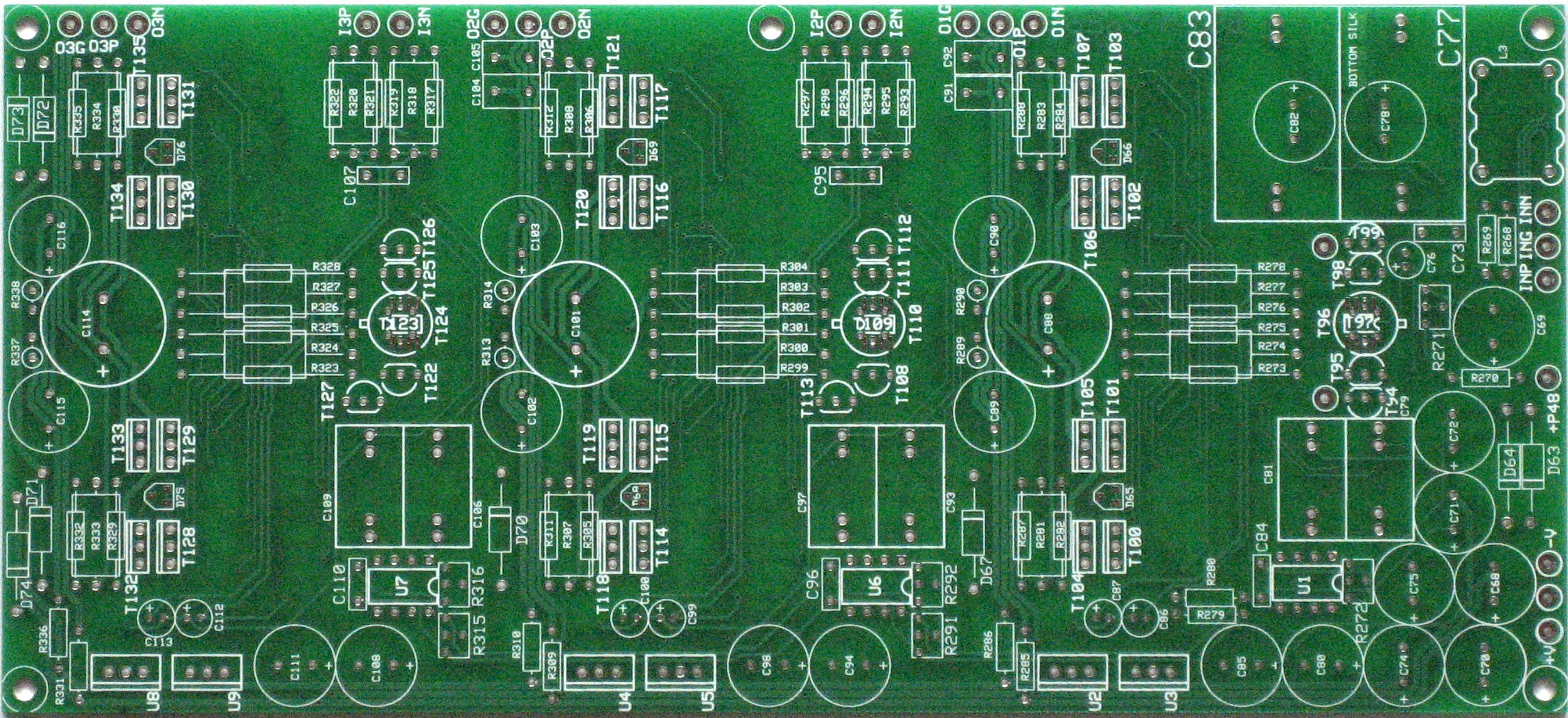
Proto layout is done. Need to touch up one or two spots and it's off to the board house. Have a look at the parts placement document to get an idea of the board and its parts.
Highlights:
- All three stages on one rather large pcb (231x105mm).
- Separate C-R-C-R supply filters for each output stage to minimize power supply loop area and inter-stage coupling through the supplies.
- Extra wide clearance between SMD parts and extra large lands to make soldering easier. Most pads aren't closer together than those on a DIP chip. Should be easier to solder than, say, a GSSL (but harder than mnats' 1176es).
- Only three different parts in SOT-23; each part has a distinct marking on the silkscreen for easy ID.
- Pads for various different input transistors. The board accommodates the MAT03 and SSM2220 matched pairs, but can also be stuffed with TO-92 transistors for the input.
- Pads for either 2W noninductive wirewound resistors or regular 0.6W metal film parts in the feedback paths, to reduce self heating induced distortion (see page 2 of this thread).
- Pads for electrolytic, polyethylene or polypropylene phantom blocking caps.
- One trimmable servo per stage, which can be replaced by a fixed trimmer.
- Pads for a common-mode choke on the mic input.
- Pads for header pins connected to the first stage's gain resistor, so that you can make the gain adjustable in the same way as the Green and the SSL9k if you prefer a more conventional approach over the proposed gain structure.
- Signal and power are routed differentially as much as possible, in a way that mycrystal ball EM field solver says should reduce both emissions and sensitivity to EMI.
I've decided to call it the 93BC. In an era of QFN-sized computer controlled mic pres a fully discrete one can be thought of as a bit stone-age, plus it has a total of 42+51 BC8x0C small-signal transistors.
Yes, that's a lot of parts; it's a bit of a monster. Fortunately most are a few cents each, and a builder who is strapped for cash can drop the servoes and the fancy Phantom caps and end up with a BOM cost of 30-40$ (without the PCB, case or power transformer). Do keep in mind that the board holds the equivalent of eight discrete op-amps (two in each of three stages, and two to set the CM operating point of the second and third stages). Also, there are many parts but only few different parts, which should help a lot when populating the board.
Need to do a few more touchups and then it's off to the PCB fab. If anyone desperately wants to see schematics at this point I'll post them, but they're a bit of a PITA to generate and if it's the same to you lot I'd rather wait until I have the inevitable proto bugs ironed out.
Comments?
JDB.
[yes, all hand-routed. Alas, my CAD package can only handle copy/paste of schematics or PCB patterns but not both, so I had to do much of the placement and routing thrice. As a result there are some minor differences between sections which could have been the same]
Highlights:
- All three stages on one rather large pcb (231x105mm).
- Separate C-R-C-R supply filters for each output stage to minimize power supply loop area and inter-stage coupling through the supplies.
- Extra wide clearance between SMD parts and extra large lands to make soldering easier. Most pads aren't closer together than those on a DIP chip. Should be easier to solder than, say, a GSSL (but harder than mnats' 1176es).
- Only three different parts in SOT-23; each part has a distinct marking on the silkscreen for easy ID.
- Pads for various different input transistors. The board accommodates the MAT03 and SSM2220 matched pairs, but can also be stuffed with TO-92 transistors for the input.
- Pads for either 2W noninductive wirewound resistors or regular 0.6W metal film parts in the feedback paths, to reduce self heating induced distortion (see page 2 of this thread).
- Pads for electrolytic, polyethylene or polypropylene phantom blocking caps.
- One trimmable servo per stage, which can be replaced by a fixed trimmer.
- Pads for a common-mode choke on the mic input.
- Pads for header pins connected to the first stage's gain resistor, so that you can make the gain adjustable in the same way as the Green and the SSL9k if you prefer a more conventional approach over the proposed gain structure.
- Signal and power are routed differentially as much as possible, in a way that my
I've decided to call it the 93BC. In an era of QFN-sized computer controlled mic pres a fully discrete one can be thought of as a bit stone-age, plus it has a total of 42+51 BC8x0C small-signal transistors.
Yes, that's a lot of parts; it's a bit of a monster. Fortunately most are a few cents each, and a builder who is strapped for cash can drop the servoes and the fancy Phantom caps and end up with a BOM cost of 30-40$ (without the PCB, case or power transformer). Do keep in mind that the board holds the equivalent of eight discrete op-amps (two in each of three stages, and two to set the CM operating point of the second and third stages). Also, there are many parts but only few different parts, which should help a lot when populating the board.
Need to do a few more touchups and then it's off to the PCB fab. If anyone desperately wants to see schematics at this point I'll post them, but they're a bit of a PITA to generate and if it's the same to you lot I'd rather wait until I have the inevitable proto bugs ironed out.
Comments?
JDB.
[yes, all hand-routed. Alas, my CAD package can only handle copy/paste of schematics or PCB patterns but not both, so I had to do much of the placement and routing thrice. As a result there are some minor differences between sections which could have been the same]
Samuel Groner
Well-known member
Great, the SYS-2722 is already warming up. What about placing the power transistors closer to each other? It looks to me as if the pairs would not touch as shown.
Samuel
Samuel
jdbakker
Well-known member
Samuel Groner said:Great, the SYS-2722 is already warming up.
It'll first have to satisfy this here 2465B. The first stage in particular has quite a bit of bandwidth, and I'm always a bit concerned about oscillations. Nothing like a nice robust analog scope to track those down.
(Some time ago we talked about why analog scopes can be more useful for analog/audio work. I was recently helping a client with an odd problem: they had an RF amp which appeared to be oscillating at 165kHz. This was rather unexpected due to the brickwall filtering of <1MHz signals. Turns out that they were using an autoranging digital scope. In reality the amp was singing at 50MHz, the 165kHz ghost they were chasing was the result of aliasing...)
Samuel Groner said:What about placing the power transistors closer to each other? It looks to me as if the pairs would not touch as shown.
They're now 3.5mm apart, some of the TO-126s I have here measure a hair thicker than 3mm. I expect that the driver and output transistors need to be screwed together (and possibly to a heatsink) before being soldered, as there's no way to get them in alignment after the fact. We'll see...
JDB.
[done tweaking the Gerbers, just sent the boards out to get fabbed]
Svart
Well-known member
Maybe it'll satisfy this here http://www.jbctools.com/advanced-series/stations/desoldering-rework/234-desoldering-rework/327-ddst-soldering-and-desoldering-station. If I can get my hands on a PCB..
jdbakker
Well-known member
Svart said:Maybe it'll satisfy this here.
It certainly will, even though that JBC is major overkill for this job (and for you, I expect you'll find this a snooze. Nothing smaller than 0805, and pads large enough to land a plane on)
Svart said:If I can get my hands on a PCB..
You will, just not yet. The Plan goes something like this:
- first I assemble a few of these, see if they work, tune compensation caps and bias to adjust for the gap between SPICE and reality
- then I send them to Samuel, to see what the SYS-2722 has to say, and adjust further if necessary
- then I get a singer/songwriter friend of mine to build one. She's never touched a soldering iron before; I use her feedback for further tweaks and/or assembly hints
- then I put out a feeler here, and depending on the response do a batch myself or ask Gustav if he's interested.
Sounds workable?
JDB.
[got the first shipment of parts in. In the end I want to have a BOM that can be fulfilled by either or (preferably) both Digi and Mouser, but for the protos I got parts from all over. Of course, now the Digi-Key shipment via UPS is playing hide-and-seek at Customs, FedEx doesn't (yet) recognize the tracking code Mouser gave me and the DHL guy carrying RS parts tried to pull his standard trick of leaving a 'you were not in'-note and doing a runner; would have gotten away if I hadn't spotted his van in front of my building. I hate parts sourcing and I loathe shipping companies!]


clintrubber
Well-known member
jdbakker said:The Plan goes something like this:
- first I assemble a few of these, see if they work, tune compensation caps and bias to adjust for the gap between SPICE and reality
- then I send them to Samuel, to see what the SYS-2722 has to say, and adjust further if necessary
- then I get a singer/songwriter friend of mine to build one. She's never touched a soldering iron before; I use her feedback for further tweaks and/or assembly hints
- then I put out a feeler here, and depending on the response do a batch myself or ask Gustav if he's interested.
It'll be more subjective than a SYS-2722 of course, but where's the step to check with ears as well ?
")
jdbakker
Well-known member
clintrubber said:It'll be more subjective than a SYS-2722 of course, but where's the step to check with ears as well ?
Part of Step 1, of course, once it passes basic tests and tweaks.
JDB.
[but this pre being designed for low-low-low-distortion and very flat phase response and all I suspect that - if everything's OK - the 'sound' of the rest of my chain will dominate. Of course I could directly drive a headphone with the output, but that wouldn't be testing it in its intended configuration]
clintrubber
Well-known member
Good to hear this is part of the plan as well. (insert thumbs-emoticon)
jdbakker
Well-known member
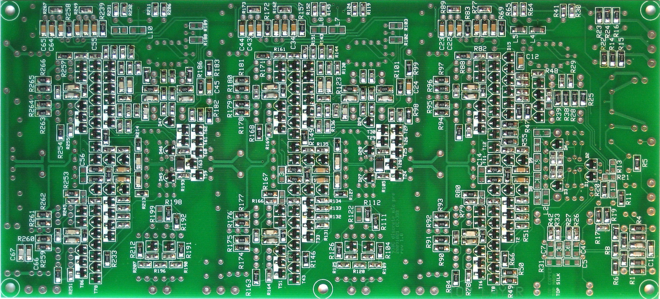
The boards and most of the parts are in.
SMD side (click to zoom):
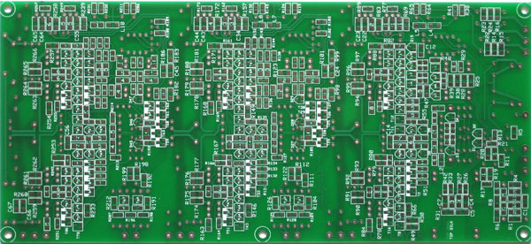
TH side:
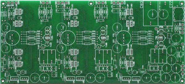
I had them done at Gold Phoenix PCB. This was my first order with them, and so far I'm happy with the result. The component print (silkscreen) registration is a bit off, and on one of the boards it's a bit smudged in a corner, but otherwise they look fine.
JDB.
[now I need to find a couple of hours to populate one, and then it's testing time]
SMD side (click to zoom):

TH side:
I had them done at Gold Phoenix PCB. This was my first order with them, and so far I'm happy with the result. The component print (silkscreen) registration is a bit off, and on one of the boards it's a bit smudged in a corner, but otherwise they look fine.
JDB.
[now I need to find a couple of hours to populate one, and then it's testing time]
ChrioN
Well-known member
Wow. Must've taken you quite some time (and skills) to design that PCB.
Svart
Well-known member
JDB knows what he's doing, that's why it looks so good.
jdbakker
Well-known member
Found some time yesterday evening to populate the SMD parts:
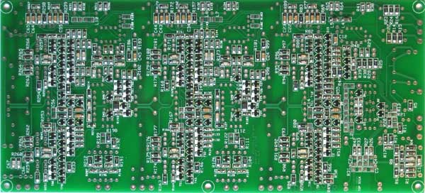
I am aware that I used a lot of solder on the pads; probably enough for a competent assembler to build three of these. Me no care. I usually farm out SMD assembly, and this is probably as much parts as I've soldered all year in my day job.
The brownish residue on some places of the board is not caused by overheating; it's what Loctite/Henkel laughingly calls no-clean flux, and was left in the spots where I used their solder braid. In a way they're right; after working with their products the boards look no clean to me...
With the components on it's easy to see that this is not a very hard board to solder. There's a lot of space between the parts and (more importantly) the pads. I deliberately tried to create some solder bridges, but that proved pretty hard, and I believe it's close to impossible to accidentally create one between SMD parts.
As you can see there are still some parts left unpopulated. These are all optional; some are there for the proto work (mostly extra frequency compensation that I hope not to need but is handy to have as a backup), some are only used if you want to go for cheap and ditch the servo in favor of a trimpot.
Populating this side of the board took me about four hours. In retrospect I could have done it faster, if only I hadn't tried to be clever.
Thing is, for placing/soldering SMD parts you really need three hands: one to hold the part (with tweezers), one for the soldering iron and one for the solder. If you only have two hands the usual approach is:
- put a blob of solder on one of the PCB pads
- put down the solder, pick up tweezers
- put the part on its pads, and use the soldering iron to melt the solder you've put on one of the pads
- remove soldering iron, hold the part steady for a second or two until the solder has cooled
- put down the tweezers, pick up the solder
- with the part now fixed on one side, solder it down on the remaining pads
This works, but I thought I could do better. Maybe I didn't need to hold the parts down? So I started placing parts on the board a dozen at a time, and soldering them all in one go. While this worked well with the SOT-23 parts and the heavier 220n 1206 capacitors, the smaller parts (predictably) started tombstoning like crazy. I believed that I could get this under control if only I'd use the right technique, and I experimented with tip placement, more/less solder on the tip, solder application, tip removal speed/angle... This would sometimes work, but not reliably, and after an hour or two I decided to wisen up and go back to the tried and true technique I've described earlier. This worked much faster, of course. Oh well, lesson learned.
As always I spent more time getting parts out of their bags, counting them and flipping them the right side up than actually soldering them. It helps immensely if you make this a team effort, with one person prepping the parts and another soldering them down. It also helps if you aren't as anal as I am and don't insist on all resistor's values being rotated the same way...
One last observation: if you're building this pre, don't use these pictures as a reference. I expect some parts changes, and for the next run I intend to simply bridge out all 0R-resistors.
Through-hole parts are next, but it appears I've forgotten to order the stuff needed to isolate the transistors from their heat sinks. To be continued...
JD "it's not OCD if you don't see a shrink" B.
EDIT: typo fix
Svart
Well-known member
looks good(and like a lot of fun).
skipwave
Well-known member
JD, your puns just slay me. ;D
And your design skills ain't so bad either.
And your design skills ain't so bad either.
breathtaking work, as always.
SNG
Well-known member
very interesting stuff to see.... can't wait to start with this too...
Brolik
Well-known member
Was hesitant about the SMD at first, but now I'm lookin to build this mostly because of getting to Try it out. Looks like fun man, thanks for all the hard work. You can definitely count me in.
Kingston
Well-known member
a gentle bump...
What happened to this project?
What happened to this project?
jdbakker
Well-known member
Kingston said:What happened to this project?
My day job happened, mostly.
I finally found some time this week to get back to the proto, and am running some nightly debugging sessions. For the moment my focus is on the first stage -- right now it's oscillating (unsurprisingly), and I'm working on fixing that plus some biasing/clipping issues.
Should anyone be interested, the schematics for the prototype are here.
JDB.
Similar threads
- Replies
- 98
- Views
- 15K
- Replies
- 43
- Views
- 7K
- Replies
- 25
- Views
- 12K
- Replies
- 183
- Views
- 52K
Latest posts
-
-
-

-

-
Modifying the Collins 356A Mic Pre for variable Negative Feedback Control
- Latest: abbey road d enfer
-

-

-
