3nity
Well-known member
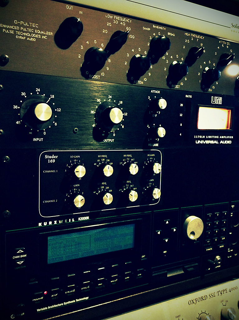
Whats wrong with the front panel???
It looks wasted
It looks wasted


MikeClev said:Could you plot one of the low boost frequencies on full boost and see if it changes at all when you change which high frequency band you have selected.
3nity said:Whats wrong with the front panel???
It looks wasted
The mastering version is the same board as the regular, just different resistors for the switches. Gustav in the WM used to sell the boards for this, message him to see if he's gonna do another run.dandeurloo said:are the mastering versions of these still for sale?
cstella said:Hi all. So after a few years I am finally building these boards!
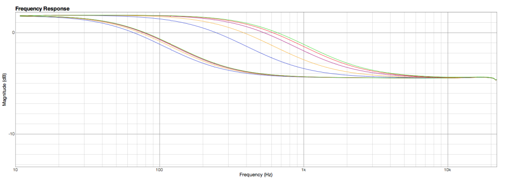
I have decided to make even smaller gain steps for a mastering version. (+/- .5 , .5 , .5 , 1 and 2dB)
I will also be adding HP and LP Filters (2 pole Butterworth) ala the BAX Mastering EQ.
Thanks to benlindell for posting the trace cuts needed. Also your tutorial on using Fuzzmeasure to do the sweeps is awesome!
http://blog.benlindell.com/?p=112
I have successfully gotten the Low Freq steps bang on by using
R3-8 = 465R +/- .5dB
R2 and R9 = 910R +/- 1dB
R1 and 10 = 1.8k +/- 2dB
and 7.5k adding to the ends using benlindell's cutting guide
I am having some problems with the High Freq though. When I try to apply the same logic I would think
135R +/- .5dB
270R +/- 1dB
540R +/- 2dB
Plus 1090 adding to the ends of the strings.
Well when I do this I don't get anywhere close to this. I have tried many combinations but I think I am missing something.
Any help would be greatly appreciated!
Thanks, Charles
Dr nEon said:Or could the mid-range filter be simply placed across pads C and D with 100uF coupling caps before and after?
")
Eje2005 said:Input straight to D, if i take the output from E (+) it´s reversed polarity
Eje2005 said:Should it help to just enter @ A/B and use that buffer?
Eje2005 said:On the I/O´s im running Cold to ground, in fact my whole system is like that.
Dr nEon said:The only issue is a 6dB level drop, typical of this situation. On other projects (e.g. Calrec eq) it was ok to change the value of input resistors, to compensate for this drop. I'd like to know if that idea could be used here, too? Or anywhere else in the circuit that could make the gain back up?
Dr nEon said:Is the first 100uF cap unnecessary?
Dr nEon said:So would it also make sense to make my coupling caps 220uF instead of 100uF
Dr nEon said:I've added a switch to bypass the midrange when I don't need it. ... It seems to be working fine, but I'd be keen to hear if anyone spots a potential problem with this arrangement.
audiox said:Unity gain, unbalanced: R27=10k
audiox said:Changes the "linear" frequency response -3dB point from approximately 1 Hz to approximately 0.5 Hz.


![Soldering Iron Kit, 120W LED Digital Advanced Solder Iron Soldering Gun kit, 110V Welding Tools, Smart Temperature Control [356℉-932℉], Extra 5pcs Tips, Auto Sleep, Temp Calibration, Orange](https://m.media-amazon.com/images/I/51sFKu9SdeL._SL500_.jpg)


