DIY home made P2P Oktava Mk012.......circuit questions & observations

GroupDIY Audio Forum

Help Support GroupDIY Audio Forum:

This site may earn a commission from merchant affiliate links, including eBay, Amazon, and others.
Alrighty, here are a couple of shots. I have affectionately named this mic "The Pipebomb". The photos aren't that great. Sorry. My space is really dark, so I had to use the flash a bit.

The scariest part of the whole build was replacing the centre wire on the capsule. When I took the capsule out of the 435, I just snipped the wires right at the capsule. I thought I wouldn't be using it again. I used 24 gauge wire because I didn't have anything smaller. I couldn't find any nice brass end caps locally, so I just used some plumbing fittings. Once I paint this sucker and build a head basket, it should look a lot nicer. For now, it works! I said above that the output was low, but it's actually not that bad. Ensemble set at 55db of gain gives me -12dbfs peak -20dbfs RMS on acoustic guitar which is perfect. Going to try this mic in front of my amp soon. Edit: Nope. Can't handle the level of a cranked amp at 1 meter. Asymmetrical clipping galore. Off axis is better, but I think this mic is more suited to acoustic instruments and vocals. For me, it's my new acoustic guitar mic.
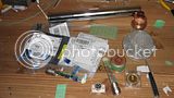
Humble beginnings

Almost there

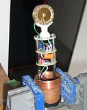
In the mount, ready to go

Good luck with those SDC's tchgtr! I think the hardest part is going to be finding a capsule that fits the body you have. I saw a mic where a guy used the Oktava pad to adapt an 012 capsule to a piece of plumbing pipe, but I can't remember where I saw that. Those 012 capsules can be found on ebay for $50 sometimes.

Edit: Cleaning up pics
 
Now that's some true DIY! Thanks for the shots. That's some pretty dicey stuff reworking the center connections on those capsules.
I have two MC-012s on which I have replaced the capsule to gate cap with polypros, and those are some of the best mics in my humble collection, as I have all three capsules for each one. Won't be using them as donors, so I'll keep my eyes open for something on the cheap side...there are a lot of SDCs on Craigslist (which probably all come from the same Chinese source), but other projects await.
Been looking at the Sony C-37A schemo and thinking...


Thanks tchgtr! I think this is my first "true" DIY project. Lots of fun so far. There were some moments with that centre wire that were freaky. Hearing the diaphragm click along the screw threads when taking the screw out was number one, and then having the spacer slide off centre when I was trying to put the screw back in was number 2. I shouldn't have had so much coffee that day.

Almost done with the head basket. I opted for 2 layers instead of just one. My inner layer has 1mm or so spacings, and the outer layer has 3mm or so spacings. The mesh came off a soup strainer, so I can't be sure of the dimensions. Testing with the second layer on showed a little more high end roll off, so I may back off the roll off in the circuit. I also noticed a decrease in room reflections, which was a nice added bonus. A little grinding here, little paint there, and I should have a decent looking microphone!

That C37A schemo is very interesting. Simple as simple can be. I wonder what capsule would be a good match for it. I want to build a tube mic in the next year or so, but not quite sure which design to go with. I was thinking royer tube mod, but that C37a may be the ticket. The capsule I would use would most likely be a 34mm 797 audio k67 type. I just can't stop modding my mics!
 
I would not build a tube CF I would build something like this

http://www.xaudia.com/xaudia/Schematics/Pages/Schoeps_Sony.html#4

I simmed a number of circuits inspired/based off the above schematic. 

Note the BJT JFET SF EF pair.  An even "better" follower design is the JFET cascode with "helper" BJT and CC source circuit you can find in in some AKG 414 schematics.  Another overlooked circuit IMO.

http://www.akg.com/mediendatenbank2/psfile/datei/51/c414B_ULS_412c87df992e6.pdf

Tube follower WHY?  If you are going to use a follower go solid state IMO.

 
  Well Gus, the idea of not dealing with tube voltage levels is very appealing. I take your suggestions quite seriously. Thanks for the link and pdf. I probably have a lot of those parts on hand. Most likely deserves something better than a Chinese capsule.
  Recently acquired a pair of used CAD E-100s that use a 9v battery for better transient response, but haven't had a chance to test drive yet.
  I was also thinking of building Rossi's China Syndrome circuit, but have a question for him about the 24v zener diode in there. Can it be any 24v zener, or must it be that one?

With all these great mic circuits around, will I ever get to building some pres....?

  I-clown...I like the Royer circuit. Easy to build, sounds VERY good as a room/drum mic. My (easily) modded MXL 2003 sounds better as a vox mic. I think Gus mentioned adding a 1G-ohm resistor to ground after the capsule on the Royer circuit, but I haven't tried it yet. Would probably sound even better with a better capsule, but it taught me a lot, and gets used in my studio.
Was thinking of putting that circuit in a M-Audio Nova body, which has one of the nicer 797 Audio capsules.
  Yeah, I too have the bug, and am very happy with the better quality of my recordings due to all I have learned here.
Kinda glad I can't afford all the hi-end stuff, so I get to take things apart... ;)
 
tchgtr

I have not seen inside a M-Audio Nova.  Have you traced it?  If not can you post a picture.  The reason I ask is maybe the circuit could be adjusted more to your taste.

With the Royer try different value plate to transformer coupling cap try .33uf to 1uf.  Again you could make it switchable .47uf and switch in a .47uf for .94uf.  .33uf and .68uf  etc.  Don't switch with power on.
 
Here are some photos.
As you can see I've replaced the capsule to gate cape with a polypro.
Assuming that the red and white wires on the amp board are the transformer, the red connects to ground, and the white to the - side of the 10uf output cap, which seems the likely place to improve the sound of this mic, which isn't as bad as some folks on the web will tell you. I've had it work fairly well on some sources like female voice, and toms. I have some nice 10uf caps, but they won't fit in this body.
I'm assuming that this is a 797 capsule due to the white ring around the membrane.


Attachments

  • Nova1.jpg
    Nova1.jpg
    131.7 KB · Views: 65
Here is what I assume to be the DC to DC board on the Nova...

Will try the different cap sizes in the Royer circuit. I think I have a 2.2uf in there now, which may not be the best choice based on what you are saying. It has a Cinemag transformer. Maybe I should take another look at their info sheet.
 

Attachments

  • Nova2.jpg
    Nova2.jpg
    129.7 KB · Views: 39
There are no active devices such as a transistor or CMOS chip on the back PCB, so it has no DC-DC converter. The polarization voltage is directly derived from P48 (or what's left of P48 with the circuit's current draw).

The circuit is probably similar to the MXL 2001 or MXL V67 type.
 
tchgtr

Can you trace the circuit?  It looks like it could be a 2 transistor JFET and BJT circuit.

What are the transistor numbers?


Rossi-thanks for furthering my education. Probably should have known that, now I won't forget it. While I have your attention...can any 24v zener be used in your China Syndrome circuit, or must it be the one called for in the schemo? THANKS!

Gus- The FET is a K30A, the PNP is a S9012. Started to trace the circuit, but ran out of time.
 
Any 24V zener will do. Note the error in the schematic: the drain resistor is 22k. The source resistor must be adjusted for proper bias just like in an KM84 circuit.
 
Thanks Rossi! I'm curious to build this.
Here it is Ryan.
 

Attachments

  • Rossichinesesyndromcircuit.png
    Rossichinesesyndromcircuit.png
    16.4 KB · Views: 140
Here's the old thread: http://www.groupdiy.com/index.php?topic=35464.0

As I said, R2 should really be 22k; the drain voltage should really be around 10V, the source voltage should be around 1 to 1.5V.

C5 determines the upward part of the HF bell curve. If your mic sounds too bright, lower the value for C5.

The transformer is a tiny Neutrik NTE4 wired backwards for 4:1.

I designed this circuit to be adjustable for specific capsules. If you want any precision in that, you have to be able to measure the mic response, though. Short of that, listen carefully and adjust.


Note: This circuit is NOT public domain. Feel free to use it, if you want to build a mic or two for yourself. For anything else, contact me first.
 
  In my case, you can rest assured that any I build are for my own use. I have no intention of getting into any business relating to mics, especially when there is so much talent around in this field. I have been curious about this circuit, and already have the 2N3819s from a recent Digikey order.
I appreciate the explanation of the circuit, and the reminder about the output transformer. Most other parts I already have on hand.
Just have to decide on a donor mic...I'm liking this Oktava circuit in my 2001, and am not ready to sacrifice the Nova. The good news is that these mics are often found used here in SoCal for decent prices...
 
Gus said:
An even "better" follower design is the JFET cascode with "helper" BJT and CC source circuit you can find in in some AKG 414 schematics.   Another overlooked circuit IMO.

http://www.akg.com/mediendatenbank2/psfile/datei/51/c414B_ULS_412c87df992e6.pdf

Hi Gus,

Would be interesting to hear about your experiences with this circuit (T101-T104).
"Better" in sim or soundwise ?

Always interested in simple topologies with a few things added for a good reason  ;)
Looks like this section addresses most of the shortcomings of a simple buffer.

Thanks,

 Peter
 
Rossi said:
Here's the old thread: http://www.groupdiy.com/index.php?topic=35464.0

As I said, R2 should really be 22k; the drain voltage should really be around 10V, the source voltage should be around 1 to 1.5V.

C5 determines the upward part of the HF bell curve. If your mic sounds too bright, lower the value for C5.

The transformer is a tiny Neutrik NTE4 wired backwards for 4:1.

I designed this circuit to be adjustable for specific capsules. If you want any precision in that, you have to be able to measure the mic response, though. Short of that, listen carefully and adjust.


Note: This circuit is NOT public domain. Feel free to use it, if you want to build a mic or two for yourself. For anything else, contact me first.

Hey, I am starting to get interested in some of these FET circuits. I have done a handful of tube mic's and I have a couple condenser mic's to experiment with also. These look very similar to the various tube circuits.

I am not interested in "modding" an existing mic per se, rather putting together some vero-board or p2p teflon-turret constructions... Using doner bodies and capsules, using the things, and of course experimenting with some higher-end capsules as funding becomes available.

When using a 3819 is it a case of going through a bag of them to identify the ones that measure (in-this-circuit-for-example) with drain of about 10V and source voltage between 1.0-1.5V? Or is it a case of tweaking the surrounding components to set the operating points? Or maybe a bit of both?

Just looking to start sourcing some bits and pieces to put maybe some of these and some other 3819 style circuits together.

The more I do this stuff the more I really dig it.

Cheers,
jb

 
It's a bit of both. You adjust the drain voltage via the source resistor, then you measure the source voltage. If it's too far off, you try another FET. Also, you have to listen for noise.

Those single FET circuits always require selection, and headroom is quite limited by modern standards (just compare max spl figures for U87 and TLM103). Getting good bias points is a way of squeezing the best possible headroom out of these simple circuits. But for the record: they still work pretty okay, if the drain voltage is a bit too high (which is often the case). You just won't get the best possible performance.
 
Thanks for the schem tchgtr, and thanks for making it available Rossi. Rest assured that it's just for my own education. I was curious about this because in my FET circuit research I hadn't come across it yet. Very interesting circuit, and those neutrik transformers are inexpensive, which makes this circuit a good one to experiment with. Might give it a go down the road, but I have another mic to build first using the km 84 circuit.

For FET biasing on the mk 012 circuit, i just set up a 2sk170, 2n5087, and R1, R2, R3, R4, R5 and R6 on a breadboard, fed in phantom power, and then measured voltages and currents to match what PRR posted a bit back in this thread. Then just swap out FET's until the measurements were good. I got lucky as my first FET/follower pair were pretty much dead on.

Anyway, here is a pic of my finished mic. The mesh wouldn't fit on the inside, so I had to build a head basket for the mic. I used some foam from a wet/dry vac filter to stuff the bottom, and I put a little bit on the capsule mounting plate as well. I think it turned out nicely all things considered. Best of all, when I put it back together, it still worked!


Decided to post a link instead of a huge pic just to keep the thread clean.
 

Latest posts

Back
Top