Gerald, no way I'm thinking you are "accusing" me. :grin: Every comment I accept as positive. BTW, this is not my project, everyone who is trying to help is inside. So, let's go! :thumb:
You are using an out of date browser. It may not display this or other websites correctly.
You should upgrade or use an alternative browser.
You should upgrade or use an alternative browser.
Diy Monitors - to build or not to build PART II
- Thread starter Moby
- Start date


Help Support GroupDIY Audio Forum:
This site may earn a commission from merchant affiliate
links, including eBay, Amazon, and others.
Hey Moby,
It may be a crasy thought:
but I've been using the D B X Drive Rak PA on a few live gigs and it has very interesting features for speaker management. What if you used that as your DSP. The converters sounded pretty transparent to me, but you can always use your own, if you want.
I know they make better models like the Drive Rak 480 or even better ones. Just look for the ones that offer the features that you are looking for. They are easy to find, and you can always try them out and return them if you don't like them.
Just a crasy thought.
I personally am not a big fan of DSP when thinking about speaker design, but if it works, it works..
[quote author="BR"]Hey Moby,
It may be a crasy thought:
but I've been using the D B X Drive Rak PA on a few live gigs and it has very interesting features for speaker management. What if you used that as your DSP. The converters sounded pretty transparent to me, but you can always use your own, if you want.
I know they make better models like the Drive Rak 480 or even better ones. Just look for the ones that offer the features that you are looking for. They are easy to find, and you can always try them out and return them if you don't like them.
Just a crasy thought.
I personally am not a big fan of DSP when thinking about speaker design, but if it works, it works..[/quote]
Cant believe! Today I was thinking about DBX drive rak. And I called my dealer for demo. 480 & 4800 are quite expensive... Only thing really bothers me is 48 khz SR. With new 96 or 192 SR DAW's monitoring through 48 khz system can really be kind of "blind". Don't know what to think about ...
It may be a crasy thought:
but I've been using the D B X Drive Rak PA on a few live gigs and it has very interesting features for speaker management. What if you used that as your DSP. The converters sounded pretty transparent to me, but you can always use your own, if you want.
I know they make better models like the Drive Rak 480 or even better ones. Just look for the ones that offer the features that you are looking for. They are easy to find, and you can always try them out and return them if you don't like them.
Just a crasy thought.
I personally am not a big fan of DSP when thinking about speaker design, but if it works, it works..[/quote]
Cant believe! Today I was thinking about DBX drive rak. And I called my dealer for demo. 480 & 4800 are quite expensive... Only thing really bothers me is 48 khz SR. With new 96 or 192 SR DAW's monitoring through 48 khz system can really be kind of "blind".
Don't know what to think about ...Thanks. I have great expirience with BSS, but this is real $$$$$ :wink:
Yes, this project was "on ice" because I was occupied with lot of recording business, but I didn't gave up. :grin: Speaker components are on the road, (thanks to Benny from Aquablue :wink: ) and I did some more consulting with Tony.
Here's some of pic's and if you need more info don't hesitate to ask :wink:
Here's some of pic's and if you need more info don't hesitate to ask :wink:


Svart
Well-known member
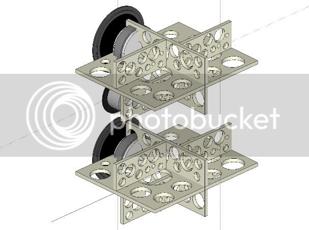
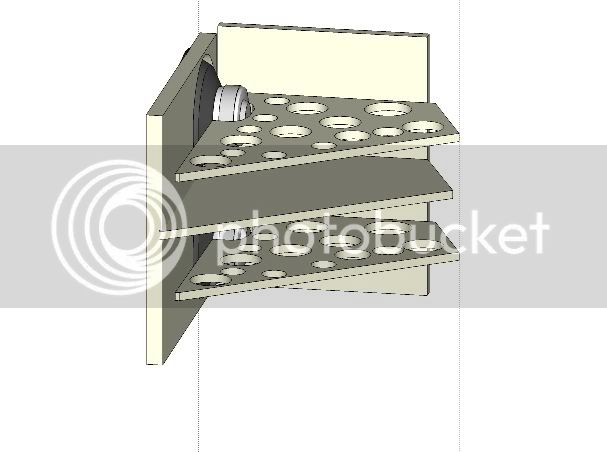
I don't know anything about speaker building.. what are the pieces with all the holes in them?
Gerald Jansen
Well-known member
[quote author="Moby"]Speaker components are on the road, (thanks to Benny from Aquablue :wink: ) and I did some more consulting with Tony.[/quote]
Hi Moby,
Which drivers did you guys choose/decide to go by? I'm curious. Lately I auditoned a WMTM incorporating for the MT-section 2 x Peerless 6 1/2 " (?), nomex (?, at least incl. phase plug) and Vifa XT25TG30 (Al front plates). That combo has high potential in my (highly subjective) regards.
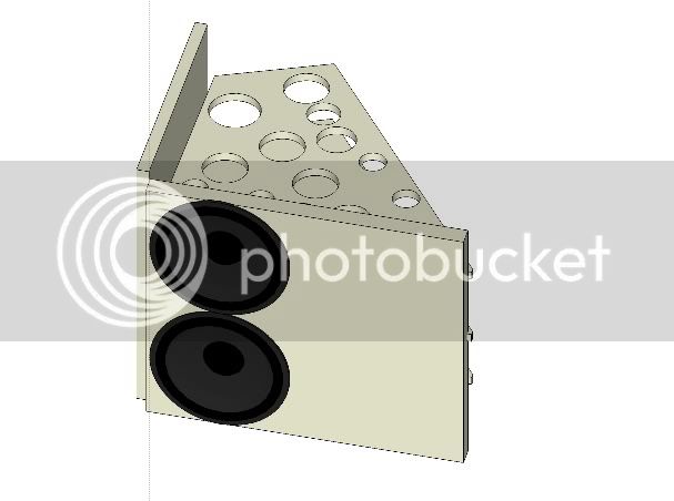
BTW, the bracings in your 3D views don't look optimal to me. The crossings between horizontal and vertical braces "include" several holes. IMO, that's not optimal for a rigid cabinet construction. Is that on purpose, or just an anomality from a quick sketchup session?
Regards,
Gerald
Hi Moby,
Which drivers did you guys choose/decide to go by? I'm curious. Lately I auditoned a WMTM incorporating for the MT-section 2 x Peerless 6 1/2 " (?), nomex (?, at least incl. phase plug) and Vifa XT25TG30 (Al front plates). That combo has high potential in my (highly subjective) regards.
BTW, the bracings in your 3D views don't look optimal to me. The crossings between horizontal and vertical braces "include" several holes. IMO, that's not optimal for a rigid cabinet construction. Is that on purpose, or just an anomality from a quick sketchup session?
Regards,
Gerald
Gerald Jansen
Well-known member
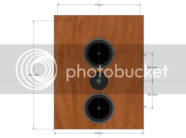
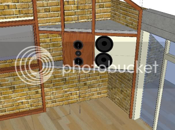
Moby, BTW, I think you should (re)consider minimizing the horizontal distance between the MTM array and your pair of woofers. Whatever X-over frequency you may end up using, the lower this distance, the less you end up with (unintentional) lobing in the horizontal plane. That should benefit the off-axis distribution of your system in the vurnerable low and mid frequency range.
Regards,
Gerald
Regards,
Gerald
Guys, thanks for comments :grin: Any comment can be useful in this project since there is a lot different approaches and experience....
Jon M has suggested a rule of thumb for the crossover frequency versus driver spacing of:
Max spacing (inches) = 13768/Crossover freq of the drivers
So, if you wanted to cross your 7" speakers to the tweeter at 1500Hz (random number, not a particular recommendation) you should attempt to keep the centre-centre distance of the two 7" drivers at no more than ~9 1/4". This formula is a rule of thumb, not an absolute. I've played with an adjustable crossover and noted the directional effects, and to my ears 'Jon's rule' is a very good target.
Thanks a lot again, and please keep commenting. Every kind of criticism is welcome :grin:
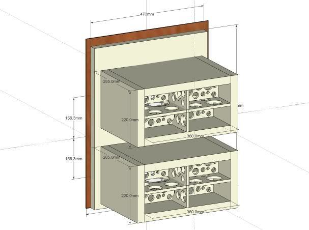
That pieces are internal braces. Use for braking standing waves and also makes box more rigid.I don't know anything about speaker building.. what are the pieces with all the holes in them?
Drivers are scanspeak 18W/8545K00 midbass in MTM setup and D2905/970000 tweeter. Woofers are peerless XXLS 308 SWR 51 147 NWP ALP DCV 8+8 ohm - 830847Which drivers did you guys choose/decide to go by
I agree, but I included the braces just to measure possible volume change. So, yes, that's a quick sketch and will be very rigid in real :wink: BTW each MTM box is sealed 15L.BTW, the bracings in your 3D views don't look optimal to me. The crossings between horizontal and vertical braces "include" several holes. IMO, that's not optimal for a rigid cabinet construction. Is that on purpose, or just an anomality from a quick sketchup session?
Hmmm, my idea was follow this idea. Not sure, and will be happy to hear some more theory about... :?Moby, BTW, I think you should (re)consider minimizing the horizontal distance between the MTM array and your pair of woofers. Whatever X-over frequency you may end up using, the lower this distance, the less you end up with (unintentional) lobing in the horizontal plane. That should benefit the off-axis distribution of your system in the vurnerable low and mid frequency range.
Jon M has suggested a rule of thumb for the crossover frequency versus driver spacing of:
Max spacing (inches) = 13768/Crossover freq of the drivers
So, if you wanted to cross your 7" speakers to the tweeter at 1500Hz (random number, not a particular recommendation) you should attempt to keep the centre-centre distance of the two 7" drivers at no more than ~9 1/4". This formula is a rule of thumb, not an absolute. I've played with an adjustable crossover and noted the directional effects, and to my ears 'Jon's rule' is a very good target.
Thanks a lot again, and please keep commenting. Every kind of criticism is welcome :grin:
[quote author="Gerald Jansen"]Moby, BTW, I think you should (re)consider minimizing the horizontal distance between the MTM array and your pair of woofers. Whatever X-over frequency you may end up using, the lower this distance, the less you end up with (unintentional) lobing in the horizontal plane. That should benefit the off-axis distribution of your system in the vurnerable low and mid frequency range.
Regards,
Gerald[/quote]
Sorry, I was half wake when posting about your comment. I was thinking a lot about and must say that this is only way in my situation because the needed MTM 60 degrees position and limiting studs of my soffit. BTW, sub crossover f will be around 90-100 hz depending from f-3 of MTM. I would like to let mid-bass drivers to go as low is possible and will not do any cut from down side (just the natural 12dB per octave below fc in sealed enclosure). So, If I include all parameters and large soffit front baffle extension, think that crossing freq. will be low enough to not be important for distance.
Anyway, let me know about if you have some other idea about. I have some time left to make some changes. :thumb:
Gerald Jansen
Well-known member
Moby,
Are you familiar with www.linkwitzlab.com ? There should be some excel spreadsheet with which you can calculate max displacement of a driver in a given enclosure. I mention this because I understand, you won't be actively filtering the MTM array and use the natural roll-off of the system. Your system may run out of breath too soon. Don't know which SPL levels you're shooting for.
My first trial would be to aim at 4th order Linkwitz-Reiley (LR) @80 Hz. That would take a 4th order active lowpass (LP) for the woofers and a 2nd order highpass (HP) for MTM array. The combined response of 2nd order active HP and 2nd order passive HP behaviour of the MTM array should "match" a 4th order LR HP filter. That may involve outdoor sweep measurements and some tweeking with the electronics.
With regards to the distance between woofers and MTM array. Wavelength-wise you can use them at your proposed distance. It may be beneficial to put absorbing foam on the vertical strip on the baffle between the drivers. That way you'll diminish secondary MF & HF reflections from the woofer surrounds and cones.
Good luck,
Gerald
Viitalahde
Well-known member
Nice sketching, I like the bracing in the woofer enclosure.
I'm gonna do this too.. I want a 3-way speaker with a "true" 300-3k midrange.
Right now I'm thinking of a biamped design with two Peerless SLS-10 woofers per side on a sealed box of about 250 litres or so with a Seas MCA15RCY 5" midrange (going to test others too) and perhaps a Morel tweeter. Active x-over for woofer-mid and a passive one for mid-tweeter. I'm going to buy a measurement mike and do it all the hard way, will be a long project.
The cabinet itself will be massive & sturdy with lots of care taken to reduce any vibrations. Once the box is right, it'll be cool swapping drivers (mid-tweeter mostly) and tweaking x-overs.
Oh, the Peerless woofer gives an f3 of a tad under 50Hz - with a 12dB rolloff (less actually) it'll kick ass.
Gerald, I searched and lurked at "linkwitzlab" but can't find anything specific about woofer displacement :sad: Can you please, please, point me or maybe mail me spreadsheet you are talking about, or do some calculation based at 100hz crossover between M and W?Are you familiar with www.linkwitzlab.com ? There should be some excel spreadsheet with which you can calculate max displacement of a driver in a given enclosure
This part I must say that I don't understand.... My baffle will be flat as possible ,say, with 1mm tolerance. Where to put foam. Between M and W? Do you have some picture as visual example of?With regards to the distance between woofers and MTM array. Wavelength-wise you can use them at your proposed distance. It may be beneficial to put absorbing foam on the vertical strip on the baffle between the drivers. That way you'll diminish secondary MF & HF reflections from the woofer surrounds and cones.
Thanks mate :wink:
Thanks, BTW I will add more vertical braces, but I was too lazy to sketchNice sketching, I like the bracing in the woofer enclosure.
About woofers Peerless 12" (830847). The double voice-coils should be wired in series on each driver (making a 16ohm driver), then both drivers wired parallel. The acceleration factor is much greater if this is done.
Also I don' believe that most of the power amps can be happy driving sub in 4 ohm's :wink:
Gerald Jansen
Well-known member
[quote author="Moby"]Gerald, I searched and lurked at "linkwitzlab" but can't find anything specific about woofer displacement :sad: Can you please, please, point me or maybe mail me spreadsheet you are talking about.[/quote]
It took me some searching, but it's still there Under the Phoenix projects/design models.
http://www.linkwitzlab.com/spl_max1.xls
[quote author="Moby"]This part I must say that I don't understand.... My baffle will be flat as possible ,say, with 1mm tolerance. Where to put foam. Between M and W? Do you have some picture as visual example of?[/quote]
I dont' have pictures, but you got the position right. Imagine a soundwave propagating towards the 2 woofers along the surface of your baffle. It will meet the outwardpointing surrounds of the woofers (+/- 10 mm ?) and the depths of the cones. These disturbances in the flat baffle produce secondary waves (diffraction) and may be audible, particularly because they are in close proximity of the MTM array in the horizontal plane. Just start your design without felt or foam. These are secondary points which may need to be addressed later if the diffraction bothers you by ear.
Good luck
It took me some searching, but it's still there
Under the Phoenix projects/design models.http://www.linkwitzlab.com/spl_max1.xls
[quote author="Moby"]This part I must say that I don't understand.... My baffle will be flat as possible ,say, with 1mm tolerance. Where to put foam. Between M and W? Do you have some picture as visual example of?[/quote]
I dont' have pictures, but you got the position right. Imagine a soundwave propagating towards the 2 woofers along the surface of your baffle. It will meet the outwardpointing surrounds of the woofers (+/- 10 mm ?) and the depths of the cones. These disturbances in the flat baffle produce secondary waves (diffraction) and may be audible, particularly because they are in close proximity of the MTM array in the horizontal plane. Just start your design without felt or foam. These are secondary points which may need to be addressed later if the diffraction bothers you by ear.
Good luck
Thanks a lot :grin:It took me some searching, but it's still there
http://www.linkwitzlab.com/spl_max1.xls
Now, I just have to figure what I'm looking for in this numbers....
Yes, I understand... I never saw this in "real" speakers, but it's worth of trying and I can do that as upgrade when I finish construction and tuning of my system.I dont' have pictures, but you got the position right. Imagine a soundwave propagating towards the 2 woofers along the surface of your baffle. It will meet the outwardpointing surrounds of the woofers (+/- 10 mm ?) and the depths of the cones. These disturbances in the flat baffle produce secondary waves (diffraction) and may be audible, particularly because they are in close proximity of the MTM array in the horizontal plane. Just start your design without felt or foam. These are secondary points which may need to be addressed later if the diffraction bothers you by ear.
And I'm thinking and searching again.... Really, cant understand problems if I do cross. frequency around 80-90hz... Look at the "proved" genelec 1035b .
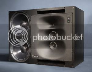
Crossover freq. between mid and bass is 400hz and distance of the drivers is similar to mine. Of course I'm not telling that 1035b's are the best in horizontal lobing, but for sure they are on the top in that aspect...
Just thinking, :roll:
Simply, don't have too much option because of existing soffit construction,
and I have not enough experience in this situation... .
But, if this issue is crucial for system accuracy I really have to find some way to rearrange.
Gerald, don't get me wrong but I don't see any connection between this calculator and speaker distance. I see that calculator is about speaker max excursion and sound pressure :?It took me some searching, but it's still there
http://www.linkwitzlab.com/spl_max1.xls
If I'm wrong please correct me :thumb:
Gerald Jansen
Well-known member
Moby, You're absolutely right. That excel spreadsheets is about volume displacement and can be used to predict the max SPL of the drivers when selecting a x-over frequency.
Please understand that I think you're working on a marvelous speakersystem and I think you'll be very pleased with the end result. It's not my intention to get you nervous. Please keep us posted.
Please understand that I think you're working on a marvelous speakersystem and I think you'll be very pleased with the end result. It's not my intention to get you nervous. Please keep us posted.
Similar threads
- Replies
- 2
- Views
- 797
- Replies
- 1
- Views
- 128
- Replies
- 45
- Views
- 4K
- Replies
- 43
- Views
- 7K