CJ
Well-known member
you guys need any info/


ruckus328 said:Dave, curious - what's the max possible voltage to the LED if using a 30:1 transformer like you've shown? I'm not very familiar with the LA2A. Looking to figure out how this approach could be tried with an LA3A, which looks like it could eliminate the step up transformer used.
")

SSLtech said:Nice and inventive!
It bears pointing out however that there are a few changes which will affect the resulting behaviour and compression characteristic.
The LED/opto caps could be the same off-the-peg solution as I used in my LA-4 clone... should work perfectly, and MUCH less work. It deals tightly around the opto, since they're slightly elastic.
HOWEVER... I hoonestly don't think that it'll behave the same as an LA-2a because of the way the LEDs are used... I've tried Parallel LEDs in the past, and found that the turn on points weren't consistent. Also, the turn on threshold behavour and the increase in light output above threshold won't be the same as an EL panel. Also, there's a particular response curve that the EL panel introduces into the sidechain, since it's a highly capacitive load. -Sweep and scope the sidechain of an LA-2a to see what I mean.
The transformer approach (a la LA3, but in reverse, so to speak) is novel, there'll be a bit of DC involved, which will doubtless place some imposition on the transformer, but I can't speak from experience, since I haven't built one.
I found that the LEDs HAD to be in series, or turn-on threshold was simply too unreliable. -I also found that I had to modify the sidechain response in order to track the rather complex LA-2a effective-ratio-versus-frequency curves. Rochey and I have had an EL-free T4 module essentially ready-to-go as a plug-in module for about 2 years, but it's taken this long to get it into a T4-sized module, which requires using SMT components. The remaining issue which is holding this back as a saleable item is opto matching and a standard test procedure.
Once that's all done, we have a product which plugs into a T4 socket, and works indistinguishably from a UA T4 module. It is El panel-free, they've been running for about 28 months and showing ZERO signs of aging. They've been left on driving 30dB compression on a tone for about 3 hours steady, trying to 'burn' or 'wear-down' the any part of the light source circuit, and so far they STILL match brand-new T4's perfectly.
In order to finish the job, we have to get the opto matching nailed down reliably and consistently... whether you're making EL-panel T4's, LED T4's or 'Turbo' T4's, that's one thing which ANY builder will always face, as Joe (Kenetek) correctly points out.
So the question arises... Who prefers the approach of making a modified circuit such as this, as opposed to redesigning the T4 module in and of itself, to eliminate the EL panel WITHIN the unit, but still allow the user to plug in a 'genuine article' T4 module, which would of course not be possible with a circuit modification approach such as this?
I'm curious as to whether we should continue to develop ours?
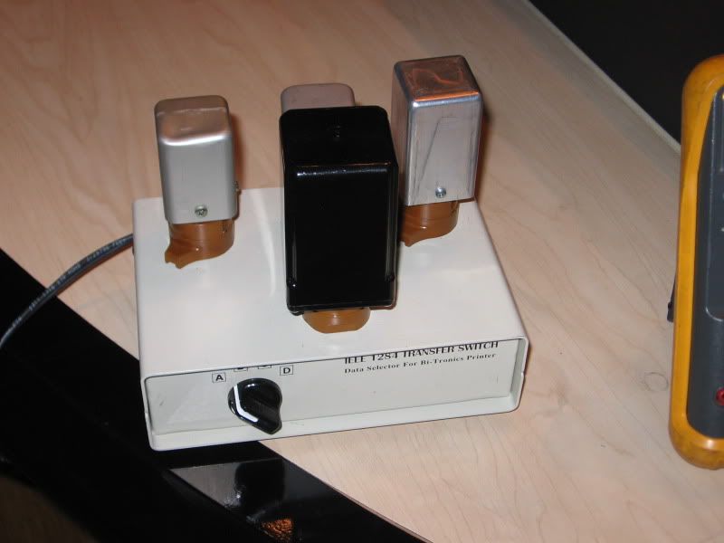
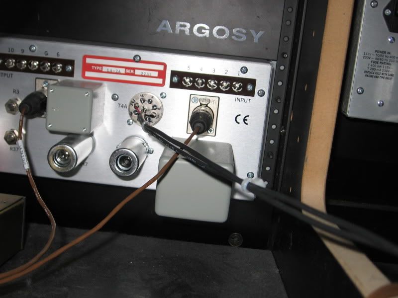
For reference, I've had this switcher box installed in a studio with two new-condition reissue LA-2a's side by side:
It's plugged into the back of one of the LA-2a's thus:
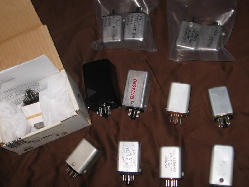
Which allows people to switch between an old-stock UREI 'vintage' T4B which is slightly aged, a used T4-A, a new Universal/Teletronix T4B, and the Expat Turbo.
Results are that most people can identify the UREI T4B and the T4A, because they have strong characteristic differences... but NOBODY has been able to tell which is the 'real' UA T4 versus the prototype 'Turbo' unit. -The switch positions are numbered, but the sockets are not, and they are sequenced in a non-intuitive order, so that people can't tell which is which by looking at the order of the devices under test.
Thoughts, anyone?
Keith
joe-electro said:Good work here. I've been fooling with all kinds of LED's for years and never got them to sound the same as an EL panel. I'd be very curious to put one of your units on my T4B tester and see what it looks like. PM me if interested.
SSLtech said:joe-electro said:Good work here. I've been fooling with all kinds of LED's for years and never got them to sound the same as an EL panel. I'd be very curious to put one of your units on my T4B tester and see what it looks like. PM me if interested.
We might be able to make that happen... Let me ask Rochey and see what he says.
Also, I might have to 'pot' the light source part first, if that's okay with you. Using OEM optos, I've had indistinguishable results. Using modern off-the shelf optos has introduced the component-selection-and-matching lottery, as I'm certain you can appreciate.
By the way, that one in the picture is the old HUGE 'development' can. -It now fits into a 'standard' can, basically identical to the Drip Electronics one. We can even switch the El panel curve emulation characteristic from standard to more-linear and overall slightly more aggressive. -Subtle effect, but useful.
I'll talk to Rochey and see what he thinks.
Keith
Will do.joe-electro said:That's cool. Just let me know.
Results are that most people can identify the UREI T4B and the T4A, because they have strong characteristic differences... but NOBODY has been able to tell which is the 'real' UA T4 versus the prototype 'Turbo' unit. -The switch positions are numbered, but the sockets are not, and they are sequenced in a non-intuitive order, so that people can't tell which is which by looking at the order of the devices under test.
SSLtech said:Will do.joe-electro said:That's cool. Just let me know.
Actually, I'm almost going out of my mind right now, clearing out the last remnants of my old workshop, and in the middle of a relocation which is driving me compeltely round the f#@%&*ing pipe!
And yesterday, to cap it all- I found a big bag of about 20 LA-2a trimmer capacitors, and spent about half an hour asking myself why I would have them...
...Ahem...
I think I was supposed to mail them to you, about three years ago.
...Sorry 'bout that!
Still want 'em? -I'll toss them in the mail if you do.
Keith
SSLtech said:...And you basically build yourself an LA-4.


![Soldering Iron Kit, 120W LED Digital Advanced Solder Iron Soldering Gun kit, 110V Welding Tools, Smart Temperature Control [356℉-932℉], Extra 5pcs Tips, Auto Sleep, Temp Calibration, Orange](https://m.media-amazon.com/images/I/51sFKu9SdeL._SL500_.jpg)


