Does anyone sell an INA217/1510/1512 PCB or have one I could etch?

GroupDIY Audio Forum

Help Support GroupDIY Audio Forum:

This site may earn a commission from merchant affiliate links, including eBay, Amazon, and others.

resilient

Well-known member
Joined
Sep 4, 2005
Messages
51
Location
Great Smoky Mountains
Hi all,

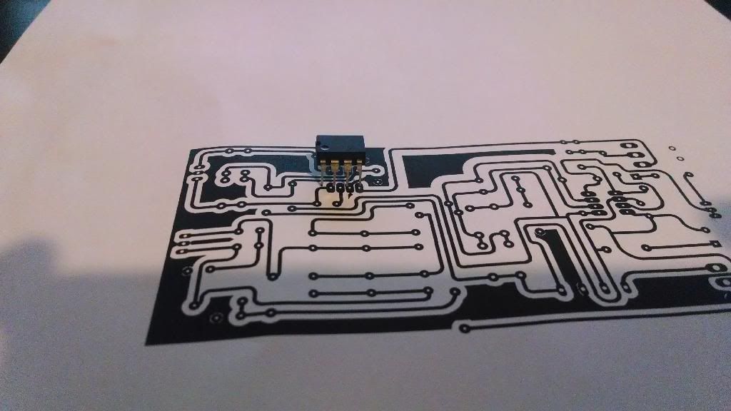
I am working on some basic preamps for my setup and I'd like to build 8 channels of an INA217 pre to use as my primary preamps.  I'll be adding a Seventh Circle for color a little later.

Does anyone know of anyone who sells PCBs for any of these chips?  Or does anyone have a PCB design they wouldn't mind sharing with me that I could etch?

Thanks!

Brandon
 
I am looking for a cheap solution.  :)  I've already got everything I need except a few caps and resistors, so I'm trying to find a PCB to either buy or etch.  :)

Thanks for posting, though!  Looks like great stuff.

Brandon
 
resilient said:
I am looking for a cheap solution.  :)  I've already got everything I need except a few caps and resistors, so I'm trying to find a PCB to either buy or etch.  :)

Thanks for posting, though!  Looks like great stuff.

Brandon

https://pcbgrinder.com/index.php?route=product/product&path=59_71&product_id=100

Theres a self etch file in the documents for this - just check the scale of the PDF. Its off, and I haven't gotten around to fixing it.

Gustav
 
Thank you for sharing this.  I had not realized the PCB was in the PDF.  You are awesome, sir.  :)  I'll do some print outs tonight and see if I can get the scale right.

Brandon
 
resilient said:
I'll do some print outs tonight and see if I can get the scale right.

Brandon

See if the scale is right on this one and report back.

Its 100% correct when I print this PDF on my own printer.

https://pcbgrinder.com/download/Check.pdf

Gustav
 
Sorry it took me so long, but I finally have an answer for you.  It did not print out to the correct scale.  A bit small.

Here's a pic:

IMG_20131205_205940344_zps8qj6kf3l.jpg


Brandon
 
I have some spare mic pre-amp pcbs which I got from Australian Technical Production Services many years ago. They use INA217 - if you are interested I could send you one from UK.

The pcbs are still being sold on Australian ebay, the seller is r-jf and the item is called
"PCBs for microphone Pre-amplifier using INA217/SSM2017 - Eight pack"
If you google that, all the info about the project and schematics etc are linked from the ebay listing.

PDF of project attached

Cliff
 

Attachments

  • Mic Pre.pdf
    9.6 MB
Seriously?! That would be awesome! I think @Gustav 's had switchable phantom power too.
Are you looking for single-sided design that you can etch yourself, or do you want to get some boards? I can do either/both. I'm looking at a turnaround from JLC of only about a week, so I should be able to have a batch made up and ready pretty quick. I would use the stock circuit from THAT, which includes a soft start phantom switching circuit that I've found works pretty well. The Five Fish preamp using the THAT chip also uses that phantom circuit.

I would include output options for either an active balanced out with an additional driver chip, or just a simple passive balanced connection, which should work fine in non-critical setups, especially if the output cable is short.
You rock! For this project, I would prefer to etch the board myself. Your proposed circuit sounds great to me, I'm hoping for a clear-sounding, general purpose utility preamp. It will always live very near the DAW interface, so the simple passive balanced connection should be sufficient.

What is your opinion of the overall sound of said circuit?
 
I have some spare mic pre-amp pcbs which I got from Australian Technical Production Services many years ago. They use INA217 - if you are interested I could send you one from UK.

The pcbs are still being sold on Australian ebay, the seller is r-jf and the item is called
"PCBs for microphone Pre-amplifier using INA217/SSM2017 - Eight pack"
If you google that, all the info about the project and schematics etc are linked from the ebay listing.

PDF of project attached

Cliff
Cliff, thank you so much for the offer. It looks like a cool project, especially the LED meter, so I've bookmarked this in case I take you up on it later. But for now, I think I'd rather etch my own. Cheers! 🍻
 
You rock! For this project, I would prefer to etch the board myself. Your proposed circuit sounds great to me, I'm hoping for a clear-sounding, general purpose utility preamp. It will always live very near the DAW interface, so the simple passive balanced connection should be sufficient.

What is your opinion of the overall sound of said circuit?
I've been using it - with fixed gain - as the front end for an original design mic pre I'm working on and it sounds very clean and neutral to my ears. The way I'm using it is almost exactly the stock circuit, except the gain is fixed.

The one thing I don't much like about the stock circuit is the necessity of using a huge electrolytic cap in series with the gain control if you're wanting to get max gain from it. Also, because the gain control resistance values at higher gains are extremely low - just a few ohms - you have to be careful about the length of the wires going to the gain control, otherwise you can get gain errors just from the tiny resistance of the long wires. But this isn't hard to overcome, it means the best way to go is to have the gain control mounted on the PCB very close to the chip itself - as close as possible. This is also one of the reasons why I chose to go with fixed gain in my design, because if it's set to only, say, 20db, the gain resistor doesn't have to be so tiny and the electrolytic cap in series with it doesn't need to be so huge. And then I follow it with a second basic opamp stage that has variable gain to get my gain control. When I'm satisfied with this design and have it finalized, I'll share it, but right now I'm still tinkering with it.

But despite my little personal issues with the THAT circuit, it is a really good sounding neutral preamp and I think there's good reason that it has become the default choice for "clean" preamps in so many commercial products.

I already posted this in another thread, but here you can hear my prototypes of the preamp with THAT front end and discrete opamp for second gain stage. No EQ on this recording:
 
Back
Top