EMI RS61 schematic?

GroupDIY Audio Forum

Help Support GroupDIY Audio Forum:

This site may earn a commission from merchant affiliate links, including eBay, Amazon, and others.
Here we go...

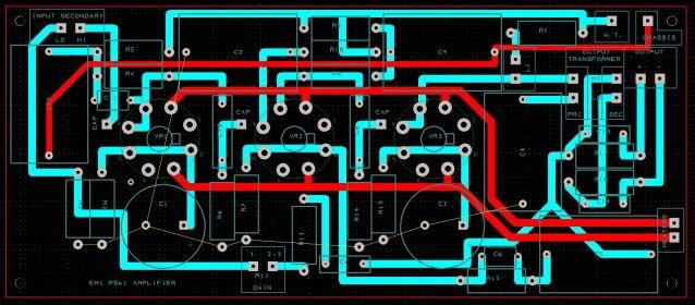
RS61BOARD.jpg


Board design from the posted schematic. Right now the layout does not include a PSU, but if someone can suggest a design I'll gladly add it to the board. The transformers are offboard, but if we can track down some pcb mount trannys, it should be easy to adjust the footprint.
 
Dustbro,
It looks like some traces weren't routed on the pcbs you posted. Is that a ground line to be wired manually?
Dan
 
dmp said:
Is that a ground line to be wired manually?

The unrouted pads go to the top layer ground plane.
I have the prototype boards in and I'm building up the first unit now to check for basic mistakes. I'll post some pic asap.
Still trying to source the iron. Brian from Cinemag was concerned about the load on a mic with the transformer on the schematic but said a CMMI-5C with a 39.2K resistor on secondary) on the input and CM-9955T on output would work.
As for the choke, any good quality 100H should do the job.
 
Very interesting project. Before you finalize the PCB layout please note there's a missing decoupling cap in the schematic, it must be connected after the 5K1 resistor going to the 72H choke and ground. A 2µF will fit but I would use a higher value like a 10 to 22µF/350V elcap, as well as for the two previous stages. Each stage must be individually declouped and this is particulary true for the last (ouput) stage where current variations are the highest. 
 
tubologic said:
Before you finalize the PCB layout please note there's a missing decoupling cap in the schematic, it must be connected after the 5K1 resistor going to the 72H choke and ground. 

I remember reading in the Radiotron Handbook somewhere that the choke will act as a decoupler, so one might not be needed in this instance. If I get any motorboating I'll know where to add one asap  :)
 
dustbro said:
tubologic said:
Before you finalize the PCB layout please note there's a missing decoupling cap in the schematic, it must be connected after the 5K1 resistor going to the 72H choke and ground. 

I remember reading in the Radiotron Handbook somewhere that the choke will act as a decoupler, so one might not be needed in this instance. If I get any motorboating I'll know where to add one asap  :)

Then you may also delete the 5K1 resistor...  a choke loaded amplifier stage can't be considered as a true constant current load and decoupling is recommended . Look at any vintage preamps of similar design (RCA OP-6 , TELEFUNKEN V72,...) and you will invariably find a decoupling cap on the B+ side of the choke load. This is just good engineering practice and a single cap will not add too much to the total cost of your project.     
 
I was comparing the early fender champ models and one of the budget cuts made on it was the choke was removed and replaced with a resistor and a cap. Is the choke in the RS61 coming from the PSU? If yes, I would assume that the same revision could be made that was made in the champ.


buildafriend said:
I was comparing the early fender champ models and one of the budget cuts made on it was the choke was removed and replaced with a resistor and a cap. Is the choke in the RS61 coming from the PSU? If yes, I would assume that the same revision could be made that was made in the champ.

The choke we're speaking about in the RS61 is not in the power supply but is an audio plate load choke. Replacing it with a resistor will seriously compromise the performance of this circuit (loss of gain,etc...)  and is NOT recommended.
 
No one? why?

look at the picture,  i guess it's not using dedicated plate choke, it's look like normal transformer, why they had paralleled primary and secondary?
I think it would be my next project... ;)


Attachments

  • rs.jpg
    rs.jpg
    316.5 KB · Views: 127

Latest posts

Back
Top