You are using an out of date browser. It may not display this or other websites correctly.
You should upgrade or use an alternative browser.
You should upgrade or use an alternative browser.
EMI TG mic preamp schematic
- Thread starter Strawtles
- Start date
Help Support GroupDIY Audio Forum:
This site may earn a commission from merchant affiliate
links, including eBay, Amazon, and others.
ruffrecords
Well-known member
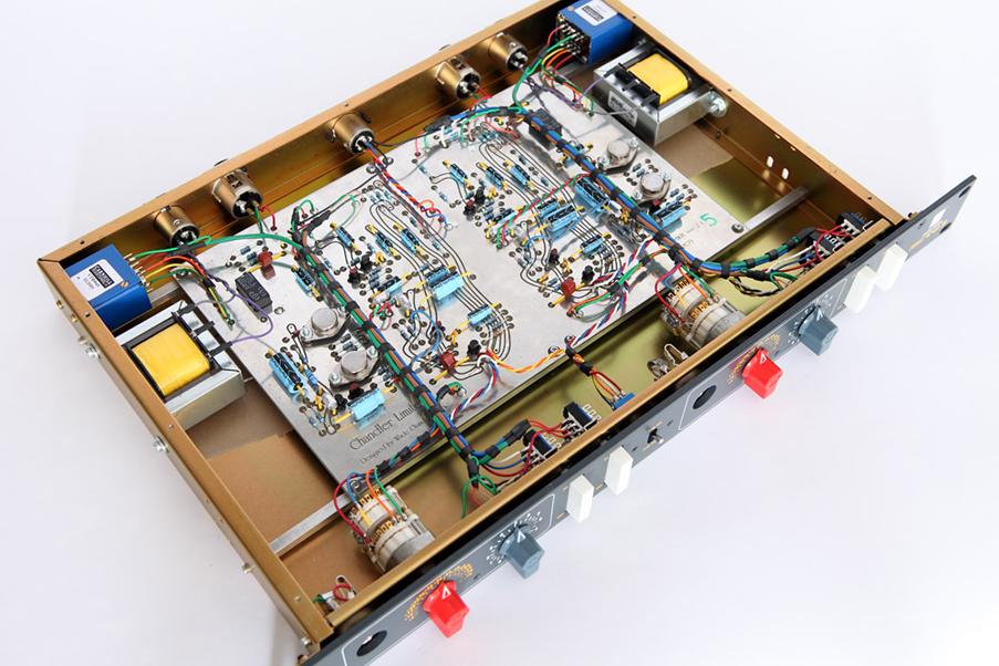
There are several threads here and at other boards asking the same question and none of them was successful. It is well known that EMI prefers not to publish them. However, Chandler have brought out authorised clones, one in 500 format. If someone has one of these it would be relatively easy to recreate the schematic.
Cheers
Ian
Cheers
Ian
Liutmod
Well-known member
- Joined
- Sep 16, 2016
- Messages
- 61
I love Abbey Road machines.
For me the REDD 47 preamplifier is the most beautiful valve preamplifier ever made and I love the TG 12413 compressor, too but after reading an interview with Geoff Emerick where he speaks very badly of the EMI TG console (and preamps) I am not too sure they are really great preamps
For me the REDD 47 preamplifier is the most beautiful valve preamplifier ever made and I love the TG 12413 compressor, too but after reading an interview with Geoff Emerick where he speaks very badly of the EMI TG console (and preamps) I am not too sure they are really great preamps
ruffrecords
Well-known member
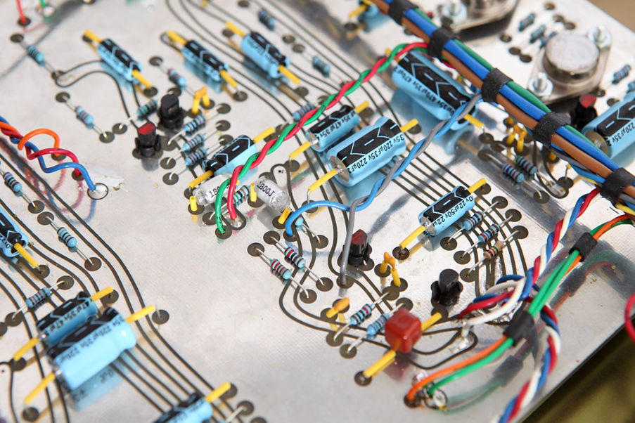
Looks to me to have about six transistors - two in the mic pre and four in the output stage. Looks like they have tried to obscure the markings on the two power transistors.
Cheers
Ian
Cheers
Ian
Yes, there are two transistors in the input stage (originally BC109 and BCY71 now BC184 and BC214) and a four transistors output stage that it is the same output stage they used in other projects.
It would be interesting to understand how the first stage is done.
It would be interesting to understand how the first stage is done.
ruffrecords
Well-known member
From what I have been able to gather from various snippets on the internet, the input amplifier consists of:
1. An input transformer with a 1:3.16 ratio i.e 10dB of gain
2, This followed by a 12 step attenuator with each step equalling. 5dB
3. The attenuator is followed by a type D amplifier with a nominal gain of 25dB. The fine gain control operates in the feedback loop of this amplifier to allow the gain to be varied from 20dB o 30dB
4. Nominal output level of the type D amplifier is -10dBV where EMI's 0dB is about 0.44V ( a left over from their 200 ohm days I think)
The attenuator therefore spans input levels from +20dBV to -50dBV (why I have no idea. Chandler porbably changed this).
I have not seen a schematic of the type D amplifier but the only description I have come across describes it as a three transistor circuit so it looks like we are a transistor short. Strangely, the description is very similar to that of the standard Neve three transistor amplifier.
Cheers
Ian
pucho812
Well-known member
If it's anything like the Neve 3 transistor amplifier, then they read the same wireless world article that others did. Apparently the 3 transistor amplifier used was borrowed from a wireless world article. They were not the not ones to use it.
ruffrecords
Well-known member
pucho812 said:If it's anything like the Neve 3 transistor amplifier, then they read the same wireless world article that others did. Apparently the 3 transistor amplifier used was borrowed from a wireless world article. They were not the not ones to use it.
That is the second time someone has mentioned a Wireless World article. I am not inclined to believe it unless someone can produce the actual article.
Back to the main topic, since this is a stand alone device, there is strictly speaking no need for the emitter follower since the preamp drives a single well defined load. So maybe the topology was changed slightly for this product. It would not be hard to do.
Cheers
ian
Hi Ian, attached you can see the second stage schematic (I found it in this forum about 10 years ago )
What is missing from the mic preamp circuit is the first stage with two transistors (BC184 and BC214) and the 12 steps attenuator.
Unlike the Neve this circuit works with a +28/-28 Volt power supply
What is missing from the mic preamp circuit is the first stage with two transistors (BC184 and BC214) and the 12 steps attenuator.
Unlike the Neve this circuit works with a +28/-28 Volt power supply
Attachments
ruffrecords
Well-known member
wlinart said:The schematic of amplifier D is posted here: https://groupdiy.com/index.php?topic=61769.msg782841#msg782841
Yes, that is almost identical to the Neve gain block.
Cheers
Ian
ruffrecords
Well-known member
Strawtles said:The input stage is different from TG 2 mic preamp that has a couple of BC184 and BC214 as confirmed in this article:
http://www.soundonsound.com/reviews/chandler-limited-tg2-500
It is probably a version of the very standard two transistor gain block (attached). The base gain is set by the ratio of R2 and R3 which can be increased by setting R4. It was common to use the PNP in the first position because of its lower noise.
Cheers
Ian
Attachments
analogguru
Well-known member
For the experts:
How does it come that the Chandler TG2 uses four transistors in the input stage ?


How does it come that the Chandler TG2 uses four transistors in the input stage ?


Similar threads
- Replies
- 5
- Views
- 962
- Replies
- 3
- Views
- 179
- Replies
- 7
- Views
- 592


