EQN build thread

GroupDIY Audio Forum

Help Support GroupDIY Audio Forum:

This site may earn a commission from merchant affiliate links, including eBay, Amazon, and others.
I've had really good luck unsoldering Grayhills with soldering "tweezers" with large (30mm) blades. I paid about $30 US for a pair, and they worked great, since you heat up all of the pins at once.
I have also had (now, the reason for the tweezers) a couple of defective Grayhill switches.  Seems that when they assembled them, they left out one of the wiper assemblies.  After that, I ALWAYS check the switches BEFORE soldering them in,
Just my $0.02 (US)
Best,
Bruno2000
 
Thanks Pete.

Is there any special requirements regarding the BC184C transistors for the Opamps. Like do they have to be matched or a certain HFE?

To minimize my chances of a noisy transistor like Mako, should I install a certain HFE transistor?
 
mnats said:
I can't remember ever being so excited to build something as this project. Thanks to Peter and all who contributed to the thread.

Mine worked perfectly from the get-go using a 51X jig, but I'm still waiting for the DC/DC converter to put it into my 500 rack. I've posted some notes on a page here:

http://mnats.net/pp-eqn_notes.html

Careless me - I lost one of the 1mm sockets for the DC converter...if anyone is building a 51X version you should have two to spare. I've got some extra bits and bobs I can trade for another socket if anyone is willing. *edit* - Sorted. Thanks to 12Volts.
Mako, in your weblink you spoke of how you discovered your opamp was the cause of a noise issue. How did you know that?
Was that
- by simple de-solder and replace and see if that was the issue
- is it a common problem solving method of noisy opamps by replacing transistor BC184C
- or you increased HFE on your transistors when you replaced them to increase your chances of solving the issue
- or something else?

Thanks
 
I don't think Mako's noise problem was related to the hfe value of the transistor, but rather due to an actually faulty component. The chance of this happening is rather low. I have built 6 EQNs (including 12 opamps) and didn't have any problems with noise. what I have heard about the BA283 stage in general (this is the output stage used in the EQN - NOT the opamp) is to use high-hfe transistors for the first BC184 in the darlington configuration, this would be TR2 on the mainboard. I usually try and find one with over 600 hfe, but I haven't actually ever made a test to see how much difference it makes. I wouldnt worry about this too much, if a transistor turns out to be faulty, just swap it out, they are not exactly expensive.
 
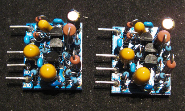
Anyone experience with this build notice anything wrong with my opAmps, like do the transistors face correctly?
opAmp2.jpg


My pin configuration for the BC184C looks like this.

Flat top
L-C-R
Curved bottom

The center leg bends backwards to fit in the PCB middle hole for that transistor?
 
Pete on your BOM it sais R19 is 7.5K. I have read people using 4.53K for R19 to get the unit working like a 1073, 1084 EQ.

Why have you set R19 at 7.5K instead. Is this a sharper or wider Q and does it sound better?
 
Pete on your BOM it sais R19 is 7.5K. I have read people using 4.53K for R19 to get the unit working like a 1073, 1084 EQ.
Why have you set R19 at 7.5K instead. Is this a sharper or wider Q and does it sound better?
This is discussed on Page 10 and then again on page 15.
 
canidoit said:
Anyone experience with this build notice anything wrong with my opAmps, like do the transistors face correctly?
My pin configuration for the BC184C looks like this.

Flat top
L-C-R
Curved bottom

The center leg bends backwards to fit in the PCB middle hole for that transistor?

Yes you will have to bend the emitter back a little bit but that's no big deal. I just compared your pic to my op-amps that just happen to be sitting here as I finished them last night and they look fine to me.  Maybe Peter can confirm though  ;D
 
JBVries said:
Yes you will have to bend the emitter back a little bit but that's no big deal. I just compared your pic to my op-amps that just happen to be sitting here as I finished them last night and they look fine to me.  Maybe Peter can confirm though  ;D
I think it's important for eagle eye overview of correct completed boards for newbies who like visual confirmation of their build. Thanks JB  :)

dmp said:
This is discussed on Page 10 and then again on page 15.
Thanks dmp, yeah I have read those posts, about the sharper and wider Q but I am very curious as to why Pete would do the 7.5K if it's not similar to a 1073/1084 setup when using the 4.53K. So I am thinking maybe its a magic EQ settings that sounds better maybe? Just want to know my options before making the solder of the part.
 
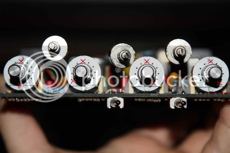
Just to make things a little easier on future builders. Make sure you have the flat part of the shaft opposite position 2 and drop pins in these locations....

12 and 6
12 and 8
12 and 5
12 and 5

Left to right...

EQN-pins2.jpg


If this is incorrect please give a shout so I can take this down but I'm pretty sure it's right.
 
JBVries, thanks, that has come in handy!

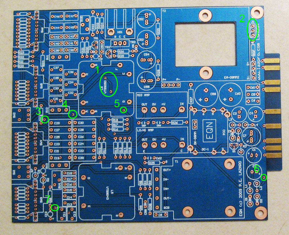
Can someone please tell me what goes to these following holes circled in green and what is the purpose of them? There are 7 of them that I have circled.
eg. 2- you put the header pins there so that you can jumper them for calibration?

eqn-unknown1.jpg


Also the HS1 heatsink's legs, are you soldering those to the PCB board? I tried soldering them but I can't get the solder to stick on the legs??


Thanks
 
Are you asking as a hypothetical question or a literal question? I think some of the holes you outlined are just left empty as they were likely part Peter's prototyping/final troubleshooting process that became superfluous to the build.

With HS1 you just gotta turn up the heat on your soldering iron. They should solder in just fine although I just did one for stability, and that way less heat is dissipated directly to the PCB.
 
canidoit said:
JBVries, thanks, that has come in handy!

Can someone please tell me what goes to these following holes circled in green and what is the purpose of them? There are 7 of them that I have circled.
eg. 2- you put the header pins there so that you can jumper them for calibration?

eqn-unknown1.jpg


Also the HS1 heatsink's legs, are you soldering those to the PCB board? I tried soldering them but I can't get the solder to stick on the legs??


Thanks


They are known as vias. They are used to transfer signal or power tracks to the opposite side or layer of a board
to make routing easier. Sometimes things are more simple than you think. :O)


Frank
 
Thanks guys!

I just don't want to miss a step.

As you know, I am not that electronically inclined as some of you folks.  ;)

Did any of you guys get nuts and bolts with your Mini 1066 transformer or EQN kit or do you have to source them yourself?
 
Back
Top