EZ Tube Mixer Support Thread

GroupDIY Audio Forum

Help Support GroupDIY Audio Forum:

This site may earn a commission from merchant affiliate links, including eBay, Amazon, and others.
I can help with getting you going on what you need. It's really pretty easy. We literally take the gerbers Ian has has so graciously shared and enter them into whichever pcb manufacter you want, I personally would choose who Ian goes to as they come out great. I can do one order with you then you will have the knowledge to do the rest.
 
matriachamplification said:
thank you.. so many questions not asked were answered here.

noted on all fronts. i had gapped on the convo with Dylan regarding this. thanks dylan.

No problem. That's what we are here for.

Cheers

Ian
 
Prima facie, I found the last post somewhat concerning. Unless I am mistaken, the Carnhill inductors you wish to use in your console are not an obselete, or no longer being manufactured part, but are still available for purchase through, for example, Audio Maintenance?

I know that plenty of reverse engineering goes on of legacy and no longer manufactured transformers, but in my opinion, reverse engineering an existing (competitors) product does not seem to be an action in very good spirit and I am somewhat surprised that Cinemag would agree to do it. I submit that maybe I don't understand the code of conduct followed by transformer manufacturers. Surely if you give Cinemag the Henries required then they could work it out how to wind the inductors themselves?

My apologies if I have misunderstood what is going on.
 
Squeaky said:
Prima facie, I found the last post somewhat concerning. Unless I am mistaken, the Carnhill inductors you wish to use in your console are not an obselete, or no longer being manufactured part, but are still available for purchase through, for example, Audio Maintenance?

I know that plenty of reverse engineering goes on of legacy and no longer manufactured transformers, but in my opinion, reverse engineering an existing (competitors) product does not seem to be an action in very good spirit and I am somewhat surprised that Cinemag would agree to do it. I submit that maybe I don't understand the code of conduct followed by transformer manufacturers. Surely if you give Cinemag the Henries required then they could work it out how to wind the inductors themselves?

My apologies if I have misunderstood what is going on.

Goodness no, and thanks for allowing me the opportunity to explain. 

we had connected with David while researching Transformers some time ago. it was during a brief convo  where cinemag discussed the open minded or willingness to guide us to other possibilities outside of Cinemag.
This willingness to aid us without reserve was awespiring and we decided to make efforts to have cinemag spearhead this area. All requests were asked partially in the gize of education, David was/is a honourable in all discussions of other manufactureres. 
That said Mr. Thompson-Bell you raise a valid perspective and  iThese are factors I need to  invest some thought into. But there was nothing nofarious intended, simply my desire to respect what Cinemag and David instilled in us about design

i can put A LOT of effort into being more tactful in a way that includes Carnhill & Audio Maintenance starting with the use of their inductors.  Apologize for not being thorough.


My intent
 
matriachamplification said:
Are there any carnhill inductors I can purchase from you? These are to be sent to David at cinemag to r/engineer for our console.
You can obtain Carnhill parts (inductors and transformers) from Audiomaintenace in the UK:

http://www.audiomaintenance.com/acatalog/index.html

As others have pointed out there are ethical issues in sending these to rival manufacturers.

However, all of the inductors have well published inductance values for each tapping point,. And may are themselves derived from designs originally created by others, e.g. the Pultec EQP1A inductor and several Neve ones. Based on that information alone I see no problem with asking another manufacturer to make versions for you. Many people have used this information to wind their own inductors and I think CJ has published the actual number of turns and core type/size for some of them. Using that detail of information would I think be a step too far.

Cheers

ian
 
@Wall

I don't know if you are following the Poor Man's Tube Mixer thread, but I just uploaded a pic of the external power supply PCB. This is one of my standard boards that I designed for the lunch box project. It will power up to 6 x EZTube Modules. Not enough to power a fully loaded EZTubeMixer but perhaps handy as a standard power supply for testing groups of modules. Anyway, I you think they could be of use I am happy to shoot you a couple in the post FOC.

https://groupdiy.com/index.php?topic=73216.msg942591#msg942591

Cheers

Ian
 
ruffrecords said:
@Wall

I don't know if you are following the Poor Man's Tube Mixer thread, but I just uploaded a pic of the external power supply PCB. This is one of my standard boards that I designed for the lunch box project. It will power up to 6 x EZTube Modules. Not enough to power a fully loaded EZTubeMixer but perhaps handy as a standard power supply for testing groups of modules. Anyway, I you think they could be of use I am happy to shoot you a couple in the post FOC.

https://groupdiy.com/index.php?topic=73216.msg942591#msg942591

Cheers

Ian

Yes! Thank you so much. I had been mulling over the possibility of a modular power supply set up for testing as well as providing to engineers along with initial prototype s we build.
I will email you a set list today with Redd Pcbs to include in the shipment. I will pay for these gladly. There is also a single part we cannot find. I will get the exact fernell part number. It's asking g me to buy 10,000 for 12 passive components. My wife says no to that kind of stock on our workbench
 
Squeaky said:
Hi, good of you to respond. Just clarifying that it was not Ian Thompson-Bell that posted.

Regards,

Nick

Sorry Nick.  I have such a small circle i communicate with. 

Good news. i contacted both Audio Maintenance & Carnhill.

We are/were already in the planning stages for  2 x Magic Eye AML kits  i think i mention it previously in this thread.

Carnhill no response yet but hopeful

in regards to purchasing from AML, this is not an option given we work directly with manufacturer’s    as per part of the libality concerns raised early on. But that is a health thing for my benifit I suspect.


ruffrecords said:
I have spent the last ten years striving to design and build clean pro audio tube preamps and mixers.....

....  A clean class A tube design shines in comparison to almost any semiconductor design; the sound is incredible.

Cheers

Ian

Please allow me this opportunity to apologise to GDIY for any annoyances or misrepresentations I may cause. I am socially ignorant and filled with preeminent personal doubt as to how to ask for help given my limited understanding of lingo and especially abbreviated terms...  but that is no excuse and from this point on I aim to be more mindful.

With a fresh outlook... the convo quoted has lead to the implementation of a 6 Channel CTC Motherboard for the Twin Line Amps to "shine."

My first query is in hopes of fully understanding the integration of Tripple Motherboard Cards.
To my understanding these are all ?terminated? or wired directly together via the MCards marked Buss section on terminal?

The hurdle I am presently conceptualizing surrounds both the in\out of the Buss "signal flow" and the integration of 3 cards into enclosures.

A. One, 2 x 6 Channel Mic Pre & EQ w\direct outs
B. 1 x 6 Channel Monitoring/Metering System

The reasoning behind this design is to make use of A as a standalone for tracking sessions and
B to facilitate Mix and Mastering sessions

This design allows for studios in various geographical locations to work with me on personal projects where I mix music or vide game audio in a Dolby Atmos 3D Audio.

To pipe in on the most recent of my research involving 3D audio monitoring systems the price tag was $11,000. Digital hardware.

The Monitor Metering section would require a Speaker Foldback System capable of addressing all the standard music and surround sound groups, but also incorporate the 7.4.1, 11 monitors and 1 Sub new standard of Atmos. The 4 stands for Ceiling speakers.

Initial designs have this laid out on individual controls for each speaker and I am having issuse with the ?relay? section for my needs.

1. Best way to group speaker selection
2. Best way to group variant Metering possibilities
3. Best use of TLA for this and headphones playback

...to be continued....


After some thought Grouping the Speakers could be easily done with a rowed selection button, kin to television boxes in the 70's with the pop switches. I have no idea what this type of switch would be called.
 
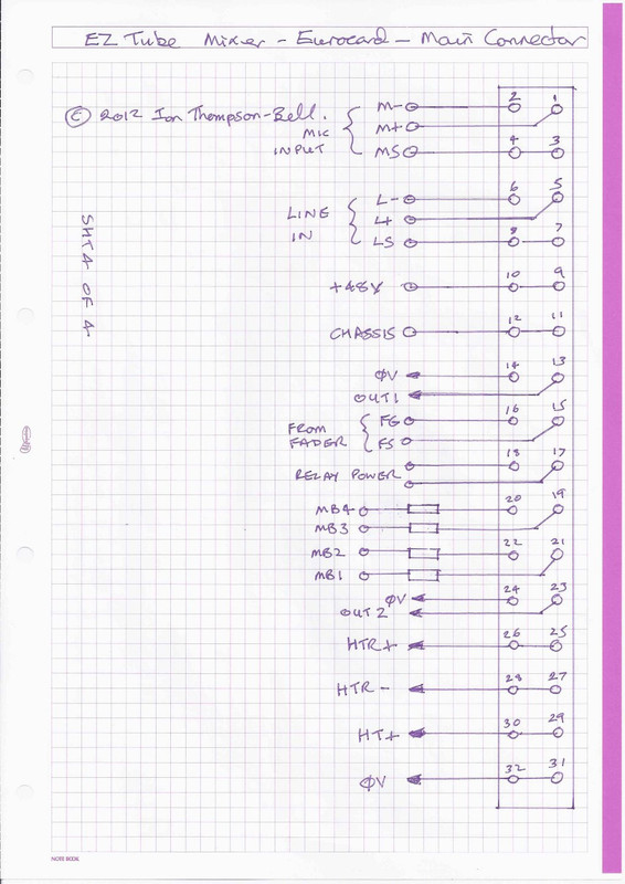
Here is the pin  out of the 32 way connector used in the EZTubeMixer Design:

Eurocard-CCTsht4.jpg


From top to bottom we have:

Mic input and line input. On the motherboard, each is wired to an individual 3 way Molex connector so you can cable them to mixer input connectors.

+48V phantom supply. Feeds the front panel mounted phantom power switch. It is bused on the motherboard. The motherboard connection should be fed with 48V from a power supply.

Chassis. This is separate from analogue 0V. The chassis connection should be wired inside modules to the metalwork of the module.  It is bused on the motherboard. The motherboard connection should be wired to a chassis bolt at the rear of the mixer where power enters.

Next we have four important connections, 0V, Out1, FG and FS, Out1 is connected to the output of the first amplifier (the mic pre) and in the EZTubeMixer design this feeds the channel fader (a 10K pot or slider). The returns from the fader go FG (fader ground) and FS  (fader slider). If you want a pre-fader direct out this would also use Out1 and is associated 0V. Internal to the module you would connect FS and FG to the EQ input.

The next 2 pins labelled relay power are left over from the early days when there was a relay switch DI input available on the Eurochannel PCB. They are no longer needed and can be used as additional buses.

MB1 thru 4 are the four general purpose buses. Provision is made on the Eurochannel PCB for fitting the necessary bus feed resistors. MB1 thru 4 are bused on the motherboard. A normal 19 inch wide  sub-rack will accommodate 6 Eurochannel modules so the standard motherboard has connections for up to 6 modules. Sometimes you do  not need all 6 so 4module and 2 module motherboards have been designed.

Hope that helps.

Cheers

Ian

The last four pins are the heater and HT supplies.
 
I know there have been some developments regarding the fischer cassette design via the MK3

Before we look into this too far, are these developments applicable to the Classic EZ Tube Mixer? Or are the Fisher cassettes with the additional supporting hardware the route to go?
 
matriachamplification said:
I know there have been some developments regarding the fischer cassette design via the MK3

Before we look into this too far, are these developments applicable to the Classic EZ Tube Mixer? Or are the Fisher cassettes with the additional supporting hardware the route to go?

I would say they are.

The original EZTubeMixer did not use Fischer cassettes. It did not even use card guides (just like API 500 series don't use them to this day). So you just held the assembly by the front panel, and did your best to locate the 32 way connector in the corresponding one on the motherboard. This proved frustrating especially during development when you are always putting modules in and out. Also, when removing modules, because the PCB was attached to the front panel only at the left hand side, each time you pulled a module you put a strain on on the PCB and often on its front panel mounted components. Lastly, although the group of six modules in a sub-rack was surrounded by an overall screen provided by the sub-rack, there was no screening between modules.

It was so solve all these problems in one go that Fischer cassettes were adopted. For the EZTubeMixer, Fischer cassettes provide the ultimate in mechanical integrity and all round screening. But they are expensive.

The Mark 3 system uses modules that are half the width of those in the EZTubeMixer so space inside is at a premium. To put this into context, the width of modules in the Eurorack system are measured in units of HP (half pitch I think it stands for) which is equal to 0.2 inches. Basically there are 84HP in a standard sub-rack. The EZTubeMixer modules are 14HP wide which is 2.8 inches so you can fit 6 of them in a sub-rack. The Mark 3 modules are only 7HP wide which is 1.4 inches - this is less than the width of a standard 500 series modules (1.5 inches) which means you can fit 12 of them in the same sub-rack. Unfortunately, the design of Fischer cassettes is such that they waste a lot of space and in fact their 7HP modules just are not viable for the Mark 3.

To provide the same degree of mechanical integrity and conquerable screening properties the Mark 3 mechanical system was devised. This makes a rigid box out of the PCB, the front panel and a steel screening plate. The front panel is attached to the left end of the front panel just like in the EZTubeMixer. The steel screening plate (the same size as the PCB) is attached to the right hand end of the front panel in the same way. The rear end of the steel plate is attached to the rear end of the PCB using pillars that mate with screws that pass through the 32 way connector. The whole forms a very strong box that is open at the top and bottom and thus allows a free flow of air over the tubes. The steel plate not only acts as an electrostatic shield but also as a magnetic one (which the Fischer cassettes do not because they are made of aluminium).

So, combined with card guides, the Mark 3 mechanical system is as mechanically robust as the Fischer modules, provides adequate screening (and in some ways better than the Fischer Modules) at a fraction of the price.

Cheers

Ian
 
matriachamplification said:
The MK3 screening looks really slick.
I will order a Fischer Cassette for reference and begin designing the EZTube Modules with the new MK3 Screening.

I just went out to the garage and came across an old EZTubeMixer Helios 69 front panel from one of my early mixers. Looking at it made me suddenly realise I need to add a couple of caveats to what I said in my last post about using the Mark 3 mechanics in an EZTubeMixer based design.

Bottom line is this will really only work properly only if you are using 3U high modules. This is for two reasons. First the 3U PCB is designed to fit into 3U card guide rails which give the module the necessary support and significantly eases locating the 32 way connector in the backplane mating half. The second reason is that you can attach the rear of the steel screening plate to the 32 way connectors using pillars.

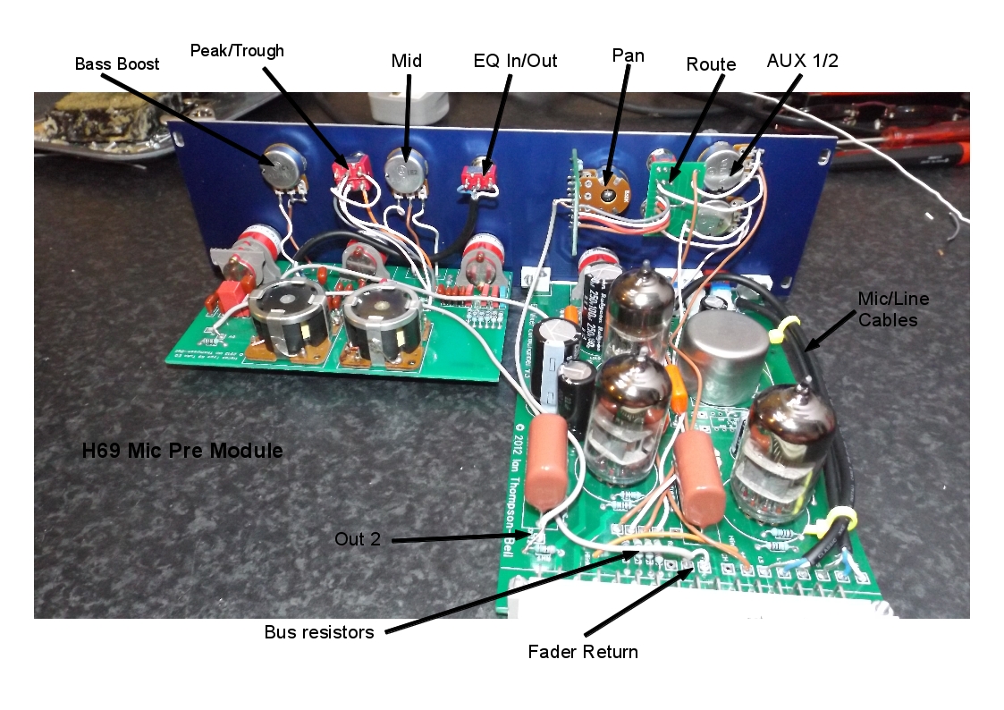
Any other option has unresolved problems. For instance, it you want to build 6U high EZTubeMixer modules in the normal way using two separate PCBs like this Helios 69 channel:

H69-Channel-Amp.jpg


then you can immediately see the problems:

1. The bottom PCB (left in the pic) does not necessarily align with the bottom card guide.
2.  The bottom PCB is not as deep as the top one so does not give the same support
3. There is no place on the bottom PCB for the pillars needed to attach the steel screening sheet.

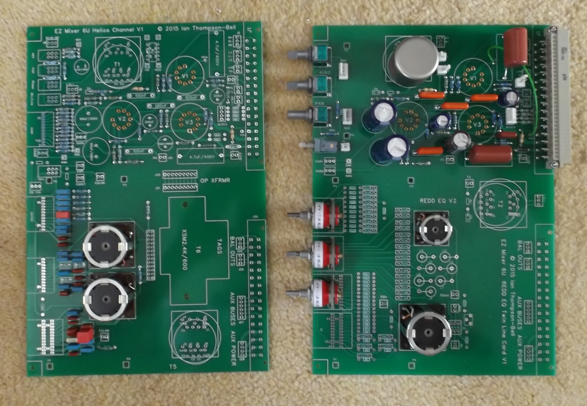
The obvious solution to these problems is to use a 6U PCB and that is initially the direction the 2nd generation EZTubeMixer was going. But it meant designing a new 6U PCB for each EQ. And every time a customer wanted something different in a module it would again require a new 6U design. Also at this time, lots of people were talking about line input mixers so the same boards would be required without the mic pres which would be another 3 PCBs to design. it looked like I would have a lot of types of PCB many of which might rarely be used. Nevertheless a couple of 6U cards were designed:

6Uprotos.png


By this time, 6U Fischer cassettes were becoming very expensive, the Mark 3 half width idea was born so the mechanics really needed a complete review. I wanted to have:

1. A low cost 3U/6U mechanical system that was robust, space efficient and provided adequate screening
2. A minimum number of different 6U PCBs along with a decoupled means of customising modules to clients requirements

Easy to say but it took a lot of time and effort to arrive at the current Mark 3 scheme. The mechanical solution I have already described. The decoupled means of customising modules is achieved by mounting a separate PCB behind the front panel. ALL the front panel controls are soldered directly to this PCB and the assembly is mounted to the front panel using the controls themselves. This means the main 6U PCB can have a standard EQ built in along with input and output transformers and a TLA. The only thing that distinguishes one customers module from another is the way these elements are connected together and the arrangement of controls on the front panel. All that is taken care of by the relatively small front panel PCB. There is a lot more detail on the development process in the Mark3 blog.

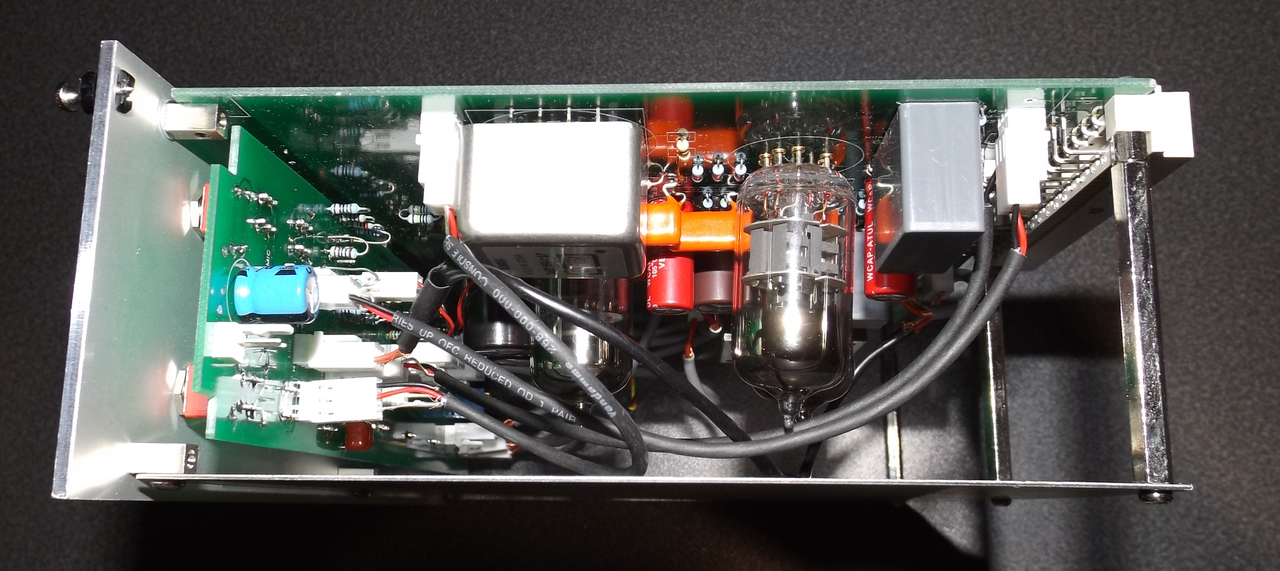
The first real test of the new scheme came in the last EZTubeMixer I built which acted as a vehicle for all the main Mark 3 improvements except the narrow width. For this mixer I designed a 6U TLA with mic input transformer, custom output transformer and a version of the REDD EQ. This PCB also used the new pin out for the 32 way connector and used the new Mark 3 backplane  and I am pleased to say it works extremely well. Here is a pic of the 6U module from the top showing how the three pillars at the back attach to the steel screening plate:

Channel-Module-Top.png


I hope this has not confused you too much. The safest approach is to build  an EZTubeMixer the old fashioned way with no mechanics at all. If you want the benefits of the Mark3 mechanics without hassles then you need to restrict yourself to 3U modules or use 3U Fischer cassettes

Cheers

Ian
 

Latest posts

Back
Top