EZ Tube Mixer Support Thread

GroupDIY Audio Forum

Help Support GroupDIY Audio Forum:

This site may earn a commission from merchant affiliate links, including eBay, Amazon, and others.
anjing said:
Ian feeding the pan card from the eurochannel card were  is it best to get the ground from? The Out2 is pretty far from CH pad...any idea? From the lower pad or the RHT?

Thanks a Lot Ian!

Pierre

There is a 0V connection right next to where the Out2 comes out on the 32 way connector. Out2 comes out on pin23 and its 0V is on pin24. I guess you are taking your Out2 from the pad right near the output capacitor so I would say it is OK to use the 0V from the bottom of RHT.

Note the ch pad is not 0V. It is intended as a way to connect to the chassis of the module - in most cases the front panel - in case the mechanical connection of the module cannot be guaranteed.

Cheers

Ian
 
Yes, it's the 3U PCB. It's plain unfilled engraving.

Beauty is in the eye of the beholder. I use unfilled engraving for back panels, but I would't use it for front panels.

Edit: It looks good on a photo. My first front panels were done unfilled, I don't like the look anymore.
 
Hello Ian!

Hope all is well with you.
The final few back ordered parts for my build have arrived at UPS and I'm picking them up tomorrow.
I'm having a bit of a problem with my HT board.
My power transformer is a centre tapped dual secondary with 120v on each side.
I am reading 240vac output from the transformer using the two outer coil leads with the centre tap unused.
How should I connect this to the board power input marked at 240v on the schematic?
I'm wondering what voltage dc I should be seeing at the HT output points?
I'm also having trouble getting the 75vdc output point to work.
I've placed the components according to the schematic provided but just to double check, could you re-post the resistor values for R1 through 4?
Thanks!
 
Mike Cleaver said:
Hello Ian!

Hope all is well with you.
The final few back ordered parts for my build have arrived at UPS and I'm picking them up tomorrow.
I'm having a bit of a problem with my HT board.
My power transformer is a centre tapped dual secondary with 120v on each side.
I am reading 240vac output from the transformer using the two outer coil leads with the centre tap unused.
How should I connect this to the board power input marked at 240v on the schematic?

Connect the two outer leads that read 240ac to the pads marked 'AC' on the HT350 power supply board.

I'm wondering what voltage dc I should be seeing at the HT output points?.
I'm also having trouble getting the 75vdc output point to work.

With no load on the output, the dc voltage across the pads labelled 'HT' will be in the region of 340 volts. Under these conditions, the dc voltage between the pad marked '75V' and the 0V pad of the HT will be around 85 volts.

Be careful when testing the power supply with no load because the smoothing capacitors take a long time to discharge - many minutes.

I've placed the components according to the schematic provided but just to double check, could you re-post the resistor values for R1 through 4?
Thanks!

The values of R1 ,R2 and R3 depend on the amount of HT current you intend to draw. This document attached shows you how to work out the values for these three resistors depending on how many EZ tube modules you need to power.

R4, and R5 generate the 75V from the HT. R4 is normally 220K and R5 is 75K.

Because the smoothing capacitors take so long to discharge when unloaded, you can change R4 to 100K and R5 to 33K to speed this up. However, this increases the dissipation in R4 which needs to be changed to a 2 watt type.

Hope that helps.

Cheers

Ian
 

Attachments

  • HTdesign.pdf
    21.7 KB
Last edited:
Thanks, Ian.
At the moment, I'm only building one unit to do some listening and testing.
My Grayhill Switch finally arrived today and the final package of parts is due tomorrow.
Hopefully I'll have it up and running for testing but not mounted in it's rack case just yet.
I am getting exactly 340 volts across the two HT pads, with no load.
However, there's no voltage at the 75 volt pad. 
I'm going to check for a fried resistor(s) or bad capacitor.
 
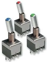
I like the buttons. For me, as dimly lit as I keep my studio, a switch is not always easy to see the position; a button on the other hand with a color insert work for me!
 
Pk/TR toggle switch certainly looks nicest for me, although probably less clear to see...

But it could look great with some of those smaller illuminated switches...the kind found on the tonelux stuff??
 
I prefer the toggle switch design. The illuminated buttons don't really suit the 'vintage' of the mixer.

42268561.jpg

I'd recommend these NKK illuminated switches but I think even they are a bit too modern looking ::)

Compromise?
 
Slightly off topic, but when I was at Neve in the 70s we only used illuminated buttons for tape machine controls. All audio modules simply had engraved key caps. The only concession to 'modern' electronics was using a separate LED to indicate when a button was pushed. When I designed the new console for the Who's Ramport studio, because they always used subdued lighting they asked if we could silk screen the modules with glow in the dark paint. We did.

Cheers

Ian
 
Wiring up a mixer is a complex business and getting the grounding right is definitely non-trivial. To help EZTubeMixer builders get grounding sorted I have written a short document explaining what you need to do and why.

Cheers

Ian
 

Attachments

  • Copy of grounding101v2.pdf
    339 KB
Last edited:
Ian, that paper is well written.

I have my first I/O module ready. Some noise figures for the Direct Out:
Line input, feeding 4 dBu, PreAmp set to 36 dB gain position which gives an output of 3.26 dBu on my first module. Then I turned the signal off.
Pre fader/EQ, after the first gain stage: noise better than -90 dBu
Post fader/EQ/after the second gain stage: slightly better than -77 dBu noise
Mic Input, feeding - 33 dBu, set amp to get 2.92 dBu output, signal stopped, input terminated with 150Ω:
Pre fader: - 89 dBu noise
Post fader: -77 dBu noise

I think I can improve the post fader numbers once my wiring is less experimental. Im using Sowter 5069 as output transformers.
 

Attachments

  • rear-cass.jpg
    rear-cass.jpg
    143.4 KB
Holger said:
I think I can improve the post fader numbers once my wiring is less experimental. Im using Sowter 5069 as output transformers.

If you have 10dB in hand on the fader plus 15dB loss in the EQ then the second stage amplifier would have a gain of about 25dB. The first stage amplifier has about 13dB of gain because the other 20dB comes from the transformer. So we might expect the second stage output  noise to be 12dB higher than the first and you measure it 13dB higher - pretty close.

The fastest way to improve the noise would be to have 0dB in hand on the fader and reduce the second stage gain - which just proves the old rule that adding an attenuator always worsens the noise. But maybe you really do need 70dB of mic pre gain???

Cheers

Ian
 
I have created a short document describing the various things the Twin Line Amp card can be used for, including a headphones amp:

(Note 2022 this PCB has now been superseded and no longer supports the use of the ECC99 for a headphones amp. In most cases the 6922 works just as well)

Cheers

Ian
 

Attachments

  • TwinLineAmpConfig.pdf
    182.8 KB
Last edited:
Hello ez-tube enthousiastes....I tough i'd share with you guys that i did  mix a few tracks for the first time today.
After spending a few weeks solving a power supply problem (with the generous help of Ian) i'm finally moving forward again.
I made a prototype of the fader face plate and tried mixing a few channels. Let's say i'm very happy!
 

Attachments

  • FirstMix.jpg
    FirstMix.jpg
    224.1 KB
Back
Top