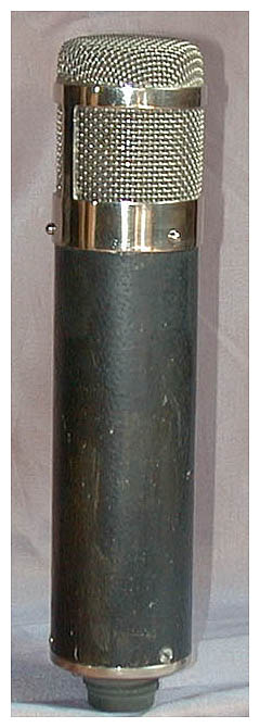
Feeler: Ela M 251 Clone

GroupDIY Audio Forum

Help Support GroupDIY Audio Forum:

This site may earn a commission from merchant affiliate links, including eBay, Amazon, and others.
Ok, so this isnt dead.

Were still working on it, sorry its taking some time we had to change a few things and work out the switching.

This is our first draft of the switching and I still need to move some things around to shorten distances and add pads for secondaries but this is where were at so far to give a sneak peak.

ELAM251V3.jpg
 
scott_humphrey said:
Since the the backplates of each side of the capsule need to be isolated for the ELA M 251 (as opposed to connected together as in the C12) I don't think that you'll be able to use the metal capsule holder that Tim Campbell supplies.  I believe that it would electrically couple the backplates of the two halves of the capsule. You would instead need a plastic, non-conductive capsule mount.
Just trying to prevent some headaches    …someone please correct me if I'm wrong.

Tim's capsule - like a real CK12 - has nonconductice rings round the backplates where the mount attaches, so the backplates are isolated also with a metal holder. That's also why the membrane on a CK12 can be completely metallized (unlike a K47/K67).
 
pasarski said:
scott_humphrey said:
Since the the backplates of each side of the capsule need to be isolated for the ELA M 251 (as opposed to connected together as in the C12) I don't think that you'll be able to use the metal capsule holder that Tim Campbell supplies.  I believe that it would electrically couple the backplates of the two halves of the capsule. You would instead need a plastic, non-conductive capsule mount.

Just trying to prevent some headaches    …someone please correct me if I'm wrong.

Tim's capsule - like a real CK12 - has nonconductice rings round the backplates where the mount attaches, so the backplates are isolated also with a metal holder. That's also why the membrane on a CK12 can be completely metallized (unlike a K47/K67).

Correct and even if it wasn't, it wouldn't be a problem to insulate it with some accurately cut electrical tape before attaching it.
 
Updated the high impedance section to make runs shorter, had to loose the top screws but I feel the two screws in the middle are sufficient ion their own in mounting the board.

Note that this is for smaller coupling caps such as the wet tants used in original Ela M models. I'm playing with the idea of the vertical cap like in Matadors C12 build.

ELAM251BRDV3.5.jpg


Cheers
 
One thing to be careful of:  in my original C12 layout, I made a conscious decision to route PCB traces to the capsule connections.  This would not normally be the way to do this:  the original mikes used floating connections to teflon standoff's using the actual leads themselves up and off the board to maintain the purity of the high impedance sections.

I got away with this by making a calculated assumption about the impedance of the FR4 material and the soldermask that's on top of it.  Ask your board house:  they will give you the worst cast impedance of this material and you can use it to make a design rule to prevent leakage currents on the board.

Eagle can enforce this rule for you:  define a new net class, and dictate a 3-5mm trace to trace and trace to plated-through-hole clearance requirement for all high-impedance traces.  I see some of your traces look fairly close to each other and you might run in to noise problems.  Assign this new net class to all capsule bias and capsule connections running through the relays, and allow Eagle's DRC check tell you how far away to move the traces to enforce the clearances.  My board house dictates 1G impedance for 2mm of soldermask over FR4, so 4mm would be 2G, 6mm would be 3G, etc.  I would shoot for 2G between all high impedance points and you should be free of leakage noises (especially if you clean the board throughly with IPA after assembly but before any styrene's go on).
 
Matador said:
One thing to be careful of:  in my original C12 layout, I made a conscious decision to route PCB traces to the capsule connections.  This would not normally be the way to do this:  the original mikes used floating connections to teflon standoff's using the actual leads themselves up and off the board to maintain the purity of the high impedance sections.

I got away with this by making a calculated assumption about the impedance of the FR4 material and the soldermask that's on top of it.  Ask your board house:  they will give you the worst cast impedance of this material and you can use it to make a design rule to prevent leakage currents on the board.

Eagle can enforce this rule for you:  define a new net class, and dictate a 3-5mm trace to trace and trace to plated-through-hole clearance requirement for all high-impedance traces.  I see some of your traces look fairly close to each other and you might run in to noise problems.  Assign this new net class to all capsule bias and capsule connections running through the relays, and allow Eagle's DRC check tell you how far away to move the traces to enforce the clearances.  My board house dictates 1G impedance for 2mm of soldermask over FR4, so 4mm would be 2G, 6mm would be 3G, etc.  I would shoot for 2G between all high impedance points and you should be free of leakage noises (especially if you clean the board throughly with IPA after assembly but before any styrene's go on).

Thanks Matador,

We're on the case. The alternative is to make the high impedance section point to point like you said, off teflon standoffs.

We made sure to use nice fat curved traces for the board and we kept our audio traces quite distant from one another but since implementing the relays things in that area got a little tight.

Going to get into the Eagle DRC this evening and see if we can straighten it out.

Cheers
 
Hi Guys,

Ok I feel like were set on the mic PCB, We feel like this layout makes the most sense. We will use thick copper 2 or 3 ounce, the cathode bypass is done on the back of the tube base.

The power supply is similar to matadors for simplicity and to replace the alctron board obviously without bias circuit and with increase in resistor value we ensure 110 B+ out

Elam251J&EV6.7.png


Just gotta wrap up the PS and tube base and we are done
 
Yep, nice body.
Firm, too.

BTW, the circuit with the 6072a is of course the Ela M 251e (Export or American version). The European version (non-e) of this Austrian mic had an AC701(k) submimiature tube. Unfortunately, those tubes are very expensive and hard to come by. But several other subminiatures are nice alternatives and those are easier/cheaper to get in good NOS quality than 6072a's, too. Poctop built his M49 and M269 circuits, both in -b (fixed bias) and -c version (self bias), around the 5840. He had good "luck" with it, to say the least. Plus the PCBs can be used for real AC701 tubes, as well, for those who are so lucky.
Anyway, would it be a good idea to make two versions of the PCB, while you're at it? Or one that could be used either way?
 
KDE said:
Not sure if this was already mentioned but Mic Bodies for this are offered by Beesneez. I'd be cool if you could taylor the PCBs to fit them like a glove!

http://www.beesneezmicrophones.com.au/store/index.php?_a=viewProd&productId=99

ELAM%20251%20style%20body%20kit.jpg
Nice but I have to say, i dont like the head basket.

Much easier to make it fit this body size. there'd be more separation between PCB traces too. Think the price is too high for most though.

Anyone down to do a body for this and we can work together?
 
micaddict said:
Yep, nice body.
Firm, too.

BTW, the circuit with the 6072a is of course the Ela M 251e (Export or American version). The European version (non-e) of this Austrian mic had an AC701(k) submimiature tube. Unfortunately, those tubes are very expensive and hard to come by. But several other subminiatures are nice alternatives and those are easier/cheaper to get in good NOS quality than 6072a's, too. Poctop built his M49 and M269 circuits, both in -b (fixed bias) and -c version (self bias), around the 5840. He had good "luck" with it, to say the least. Plus the PCBs can be used for real AC701 tubes, as well, for those who are so lucky.
Anyway, would it be a good idea to make two versions of the PCB, while you're at it? Or one that could be used either way?

Thats the version I'll be testing first. Its the exact same circuit with the exception of a few component value changes in the mic and also PS to give heater 4v.

We planned to include an additional tube mount board catered for the AC701 type.
 
JessJackson said:
KDE said:
Not sure if this was already mentioned but Mic Bodies for this are offered by Beesneez. I'd be cool if you could taylor the PCBs to fit them like a glove!

http://www.beesneezmicrophones.com.au/store/index.php?_a=viewProd&productId=99

ELAM%20251%20style%20body%20kit.jpg
Nice but I have to say, i dont like the head basket.

Much easier to make it fit this body size. there'd be more separation between PCB traces too. Think the price is too high for most though.

Anyone down to do a body for this and we can work together?

I would guess this will be most accessible if your PCB, like Chunger's, fits the Apex bodies. I have a pair set aside that I'm hoping to use for this build.
 
Dylan W said:
I would guess this will be most accessible if your PCB, like Chunger's, fits the Apex bodies. I have a pair set aside that I'm hoping to use for this build.

Yeh it fits perfect Dylan... thats my sons name lol.

Think i'm going to keep it for that body unless someone can do a custom for this build. its just round the corner now.
 
There have been several different incarnations of the Ela M.
Here's one that may look butt ugly to some and peasantly different to others:

usa20_06.jpg


On this one at least you don't need the pencil trick to stop plosives.  8)

More here:
http://www.coutant.org/akgc12/

In any case, Ela Ms are always fatter than C12s.
 
micaddict said:
There have been several different incarnations of the Ela M.
Here's one that may look butt ugly to some and peasantly different to others:

usa20_06.jpg


On this one at least you don't need the pencil trick to stop plosives.  8)

More here:
http://www.coutant.org/akgc12/

In any case, Ela Ms are always fatter than C12s.

It says in the article that the black mic is not an AKG or Telefunken, but a Thiele modified to be similar to the ELA M251.

-James-
 
Hello Everyone,

Hope this is OK to post here. I have just asked Veronica about the possibility of doing a group/bulk buy of Beesneez ELAM 251 bodies (identical to their Tribute 2 mic body). We are still to iron out details re costs, postage and minimum numbers etc but Veronica has offered them for a significant discount off usual list price. Additionally, if we get back to her in the next couple of weeks, then the ETA for shipping would be early October.

So please keep an eye out for a feeler thread in the white market soon with updated details.

The information regarding this can now be found at the end of the Beesneez capsule thread in the white black market.

http://www.groupdiy.com/index.php?topic=52326.msg681964#msg681964

http://www.groupdiy.com/index.php?topic=53469.0

Cheers,

Matt
 
Will the P.S.B. kits include the Power Suppy boards like Madador's C-12 kit.
Same HT-11A Modified Power Supply?
Besides AC701, what tube 5840, or what?
Will there be a parts kit? or will Chunger's C-12 parts kit work?
Making decisions to build a pair.
 

Latest posts

Back
Top