Official C12 - Ela M / Build And Support Thread

GroupDIY Audio Forum

Help Support GroupDIY Audio Forum:

This site may earn a commission from merchant affiliate links, including eBay, Amazon, and others.
jrmintz said:
It works great! I can't tell from my own voice if it sounds like any of the good 251s I've used, but it certainly has a nice tone. That's saying a lot with my voice. I have some good singers in next week to try it out on.

I realize now why I was having the spitting and hissing problem - I hadn't removed the direct wire from cathode to ground before adding the 20uF cap and 1.82k resistor. So I was running them in parallel. I finally grasped that after staring at the schemos long enough.

Anyway, thanks Matador, thanks 'Chung, thanks Jess for your schemo.

Awesome!

I added a much clearer schematic into the official C12 thread.  I'll link to it here for completeness:
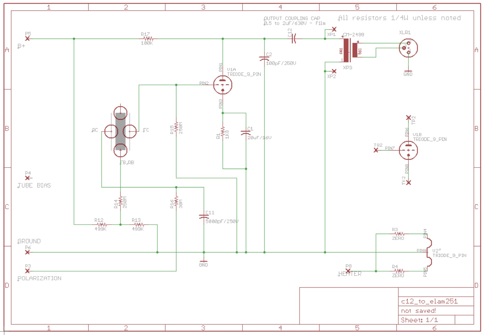
c12_to_ela251_v2.jpg


Like I said in the other thread, if you don't want pattern switching and just want to make the mike cardioid only, you can also remove R16 and C11 and just let the RC connection float (like a U47).
 
I just figured out that 2.2uF Xicon Metalized Polypropylene (I got them from Mouser) caps will fit in the output cap space, so if you're looking for a larger value this will fit.
 
Great work Matador and Chunger!!! love you work guys! I've been modding Apex 460 types with the C12 and Ela M 251 Circuts for a while now and I just thought I would contribute something that could be added to your ELA schematic Matador and that's the 4700pf bypass Cap to ground after R14 to ground like the original Ela circuit has. It's a day and night difference.. more aggressive sound with hyper 3d transients  ;)
 
Hi Matador,

So Last night i modded my c12 into elam type and noticed a couple things

In your schematic, you have the FC going to grid and FB going to plate / B+, (I have RC and RB floating for pure cardioid as in elam 251)

In the Elam 251, FC is going to plate / B+ and FB is going to grid.

I modified the additional parts of the board to reflect an exact 251 circuit with the exception of 20m resistor instead of 8meg at FC.

looking at a ton of schematics, it seems that the elam is the only mic wired this way... is there any benefit wiring the capsule the opposite way as per, c800g  u47 u67 c12 etc... ?

cheers
J
 
OPR said:
Great work Matador and Chunger!!! love you work guys! I've been modding Apex 460 types with the C12 and Ela M 251 Circuts for a while now and I just thought I would contribute something that could be added to your ELA schematic Matador and that's the 4700pf bypass Cap to ground after R14 to ground like the original Ela circuit has. It's a day and night difference.. more aggressive sound with hyper 3d transients  ;)
Chiming in rather late here ---
doing a lotta reading trying to understand the subtle differences in mic design, cacpsule usage and the such, so that being said i like what OPR has to say here, but for the life see where R14 ties to ground. R14 appears to be part of the voltage divider R12-R13 from the B+ rail, floating above ground by R13. i am new to this so please enlighten me.
thank you,
lance
 
Hi!

Are there any build photos floating around regarding the capsule connections for the 251-style build, keeping intact the remote polarization? 

I have the C12->251schematic Matador posted but would love to see photos of the physical connections between the capsules and the board for extra clarity!

From the schematic, I think the connections are:

(1) FC -> FB on the circuit board, with a jumper to replace C13
(2) R15 tied to ground (or to tube bias set to 0V?)
(3) R11 and C10 are also removed
(4) FB& RB (tied together at capsule) ->RB on the circuit board
(5) RC ->RC on the circuit board
(6) RB on the circuit board is unused

Correct?

Thanks so much,

Damon
 
digitall2000 said:
OPR said:
Great work Matador and Chunger!!! love you work guys! I've been modding Apex 460 types with the C12 and Ela M 251 Circuts for a while now and I just thought I would contribute something that could be added to your ELA schematic Matador and that's the 4700pf bypass Cap to ground after R14 to ground like the original Ela circuit has. It's a day and night difference.. more aggressive sound with hyper 3d transients  ;)
Chiming in rather late here ---
doing a lotta reading trying to understand the subtle differences in mic design, cacpsule usage and the such, so that being said i like what OPR has to say here, but for the life see where R14 ties to ground. R14 appears to be part of the voltage divider R12-R13 from the B+ rail, floating above ground by R13. i am new to this so please enlighten me.
thank you,
lance

I would also like to know about this and am also a newbie here.
Where do you place the 4700pf bypass Cap?

Thanks!
 
It goes right "after" R14, which is the node that attaches to the bridged backplates in my modified schematic.

The user ValveTone has found an interesting effect of my modification:  I adapted the polarization scheme to match that of the U47, which keeps the 0V biased membrane facing the singer.  I always liked this because it minimizes contamination of the front membrane from ionized particles like dust, spittle, etc.  Having 0V potential serves as a shield for thing (other mikes like the G9 use a similar scheme).

However if you look at the original ELA M251 polarization table:

ModeFCFBRBRC
Cardioid+60VGND (via grid)floatfloat
Figure 8+60VGND (via grid)GND+60V
Omni+60VGND (via grid)short to FB+60V

You'll notice that the polarization voltages are opposite my scheme.

There is no harm in this, the capsule won't care one way or the other, however the side effect is that the omni and figure-8 modes on this conversion will be "swapped", so that holding the rear membrane at 0V will render a figure 8 pattern, and bringing it to 120V will yield an omni pattern.  So the switch on the PSU won't match the pattern being used.

The fix is simple:  swap the outer two wires on the PSU three-pin connector (the farthest connector to the left) which connects to the pattern switch.  This will swap the order of the voltages and make the patterns match the PSU front enclosure markings.
 
Matador said:
It goes right "after" R14, which is the node that attaches to the bridged backplates in my modified schematic.

thanks matador,
not to be too dense here, but that is the node where R12-R13-R14 connect to each other,
and would be from that node, a 4700pf cap directly to ground ?

so could this also be viewed as being paralleled across R13 ?

i really appreciate all your and chungers work on this and the C12 version
thanks again,
lance
 
digitall2000 said:
Matador said:
It goes right "after" R14, which is the node that attaches to the bridged backplates in my modified schematic.

thanks matador,
not to be too dense here, but that is the node where R12-R13-R14 connect to each other,
and would be from that node, a 4700pf cap directly to ground ?

so could this also be viewed as being paralleled across R13 ?

i really appreciate all your and chungers work on this and the C12 version
thanks again,
lance

No that is the "other" side of R14.  You want the side that feeds the 60V backplate voltage to the capsule, which is "downstream" of R14.

IOW, not the side of R14 where R12/R13/R14 meet, but the "other" side.
 
Matador said:
digitall2000 said:
Matador said:
It goes right "after" R14, which is the node that attaches to the bridged backplates in my modified schematic.

thanks matador,
not to be too dense here, but that is the node where R12-R13-R14 connect to each other,
and would be from that node, a 4700pf cap directly to ground ?

so could this also be viewed as being paralleled across R13 ?

i really appreciate all your and chungers work on this and the C12 version
thanks again,
lance

No that is the "other" side of R14.  You want the side that feeds the 60V backplate voltage to the capsule, which is "downstream" of R14.

IOW, not the side of R14 where R12/R13/R14 meet, but the "other" side.
well in rereading your original placement statement i guess i can be too dense, so thanks
again for the clarification. i take it when you say "after R14" you mean as the voltage flows.
in looking at the schematic above the bypass cap goes from where R14 connects to FB,RB
to ground, essentially bypassing R14,R13 ?

thanks again,
lance
 
Matador said:
It goes right "after" R14, which is the node that attaches to the bridged backplates in my modified schematic.

The user ValveTone has found an interesting effect of my modification:  I adapted the polarization scheme to match that of the U47, which keeps the 0V biased membrane facing the singer.  I always liked this because it minimizes contamination of the front membrane from ionized particles like dust, spittle, etc.  Having 0V potential serves as a shield for thing (other mikes like the G9 use a similar scheme).

However if you look at the original ELA M251 polarization table:

ModeFCFBRBRC
Cardioid+60VGND (via grid)floatfloat
Figure 8+60VGND (via grid)GND+60V
Omni+60VGND (via grid)short to FB+60V

You'll notice that the polarization voltages are opposite my scheme.

There is no harm in this, the capsule won't care one way or the other, however the side effect is that the omni and figure-8 modes on this conversion will be "swapped", so that holding the rear membrane at 0V will render a figure 8 pattern, and bringing it to 120V will yield an omni pattern.  So the switch on the PSU won't match the pattern being used.

The fix is simple:  swap the outer two wires on the PSU three-pin connector (the farthest connector to the left) which connects to the pattern switch.  This will swap the order of the voltages and make the patterns match the PSU front enclosure markings.

Hi Matador, I can't figure out for the life of me why your mod would be opposite your C12. Or maybe you are not saying this?

In the C12, the FC is grounded, and the RC is varied between 0V (omni) and 120V (bi-directional). In your C12-to-251 mod, it looks like FC is also grounded (by being tied to the grid), but we still vary 0V to 120V on RC. How would this result in opposite patterns for omni and bi-directional than the C12?

Secondly, in the original 251 polarization voltage table, I fully understand how they're getting cardioid, but it seems to me like the Omni voltages and bi-directional voltages would result in the same pattern. What am I missing? We're looking at a difference 60v from the diaphragm to the backplate on each side in both cases. But in Figure of 8 one of the sides needs to be inverted polarity, and I don't understand how they're getting it.

Thanks!
 
There is a key distinction however:  the distinction is the impedance delivering the potential.  If you look at my previous posting in the other thread it gives a clue:

[quote author=Matador]
Figure-8 and omni look suspiciously close together, however the secret between them is:  for figure 8, the +60V connection is isolated from the +60V supply to the FC via a low-pass filter (the resistor and cap in the capsule assembly).  Thus the capsule looks like two, "2-terminal" cardioid capsules stuck "back to back".  However in omni, the FB and RB connections are shorted together, and the FC and RC nodes are shorted together.  So now it looks like a 3-terminal capsule in a regular omni-biasing scheme.
[/quote]

Notice in the C12 circuit, the FC node is hard grounded (via the sub-ohm impedance of the wire to ground).  In my E251 conversion, yes it is at ground "potential", but is being transmitted via the 250M grid resistor, so it's a high impedance node now. 

It's a critically important distinction:  in order for the different capsule nodes to be electrically dependent, they have to be joined via an impedance much lower than the source impedance feeding the amplification stage.  Taking a wire from a capsule to circuit ground essentially guarantees that the electrical potential of that piece of the capsule *cannot* be disturbed, because the impedance to ground is essentially 0 (ok...sub 1 ohm to be exact).  The charge on that piece can *never* change.  Now in the modified scheme, the 0V potential is held very "loosely" to ground potential, and is free to be modified by the polarization voltages of the other membranes.

So even though the polarization voltages might be the same as the C12, they aren't equivalent due to the source impedances.  When the back membrane is switched to 0V, it exactly matches the same configuration as the ELA M251 (although opposite polarity), including the source impedances, for figure-8 mode.

Hopefully that makes sense.
 
Hi interesting reading , I have couple of Elam251 schematics original grid resistor was a low 30M... that would make the mic lack in bass right a couple years ago I prototyped one & Im sure it sounded crap but the original mic was said to be a great vocal mic... did I read it was designed for german radio, were the ones used for vocals modded like now I see 250M on the grid ....also the R14 is 250M is that a better sound ?

On the two schemtics I have one has 1uf output cap other has a 3.2uf was that to pass more bass ?

Many thanks
 
I would like to replace the output transformer of the mike with a balancing circuit. Has anybody thought of this.
I just hate the sound of transformers.
I had the tech at one of the studios I owned take all the Transformers out of an API board.
This took him a long while as we were still using the console. We lost 6db gain but the overall sound was astonishing.
Any ideas.
Spencer
 
spencer26 said:
I would like to replace the output transformer of the mike with a balancing circuit. Has anybody thought of this.
I just hate the sound of transformers.
I had the tech at one of the studios I owned take all the Transformers out of an API board.
This took him a long while as we were still using the console. We lost 6db gain but the overall sound was astonishing.
Any ideas.
Spencer

Look at the venerable Shoeps transformerless output circuitry. I have to say you are in the minority on this but there are solutions that don't include transformers.
 
Matador said:
hitchhiker said:
Matador said:
Ok, does this make sense?

C12 to ELAM251 capsule

Would  an elam 251ish built to this Matador linked schematic that omits  C1 & R1, ( 20uF  & 1K8 as shown in Matadors later posted schematic) have any issues?

It wouldn't work at all without R1 and C1. :)  They have to be there to provide the bias voltage.


Thank you Matador for the quick response!
 
digitall2000 said:
Matador said:
digitall2000 said:
Matador said:
It goes right "after" R14, which is the node that attaches to the bridged backplates in my modified schematic.

thanks matador,
not to be too dense here, but that is the node where R12-R13-R14 connect to each other,
and would be from that node, a 4700pf cap directly to ground ?

so could this also be viewed as being paralleled across R13 ?

i really appreciate all your and chungers work on this and the C12 version
thanks again,
lance

No that is the "other" side of R14.  You want the side that feeds the 60V backplate voltage to the capsule, which is "downstream" of R14.

IOW, not the side of R14 where R12/R13/R14 meet, but the "other" side.
well in rereading your original placement statement i guess i can be too dense, so thanks
again for the clarification. i take it when you say "after R14" you mean as the voltage flows.
in looking at the schematic above the bypass cap goes from where R14 connects to FB,RB
to ground, essentially bypassing R14,R13 ?

thanks again,
lance

Hi guys, Can someone please clarify the placement of this cap. I have converted my C12 to ELAM251 as per this thread all is working well until I add the 4700pf cap from r14 to ground. Basically the patterns no longer function and the mic always stays in cardiod mode with the bypass cap in place. I'm just using a cheap ceramic cap. At first I though it was a dodgy cap so tried another and after testing  a few others still no go. I must say tho with the cap in place the mic is transformed. Would a bipolar cap be the best fix for this situation?

Cheers
 

Latest posts

Back
Top