Feeler: EZ Tube Lunch Box

GroupDIY Audio Forum

Help Support GroupDIY Audio Forum:

This site may earn a commission from merchant affiliate links, including eBay, Amazon, and others.
G-Sun said:
ruffrecords said:
I think if you are prepared to go with an external power supply you should be OK. I don't know enough about the actual circuit to be able to comment on the HT voltages.
Cool.
But, it's not something you see yourself incorporating into the EZ Tube Lunsh Box project?

btw: What does EZ stand for? :)

No, it is not something I see incorporating into the Lunch Box project. I will eventually design a compressor when I get the time.

EZ is short for easy.

Cheers

Ian
 
I'm thinking,

if I am to use a 2ch unit on masterbus, it would be
a) for tube-sweetning
b) for compression
But, then stepped switches are almost mandatory
and the compressor would need decent stereo-tracking.
Comp would ideally have a veryFast/fast and  fast/verySlow opto, with mix between them. 3:1 soft knee is close to perfect for most things I'd like to do. Vari-mu optionally.
A VU-meter with in/gr/out would be very good.

I could of course use 2ch preamp for sweetening only, and it would be easier to gainstage right without stepped pots  (eq is not typical what I would apply for mixing masterbus). That would leave a 1ch compressor as optional for tracking.
For tracking, stepped is not so important.

I need to have these things clear, especially for deciding between 5 or 6 slot chassis, and internal or external psu.
Deciding pre/eq/comp or pre/eq and separate comp is also a thing.

A 2ch stepped pre/eq/comp would seem like ideal, but might not be possible.
Everything else is a little less ideal.
 
So, is your idea to use this principally as a bus tool working at line level or will you be using it for tracking as well?

Cheers

Ian
 
ruffrecords said:
So, is your idea to use this principally as a bus tool working at line level or will you be using it for tracking as well?
Tracking and masterbus.
But, if it turns out less ideal for masterbus, then 1ch for tracking only would of course be very usabel.
Then 5 slot rack with psu in last slot or mounted in the back.

Yet, seeing my limitations, I'm taking my time with this one.
 
... I will eventually design a compressor when I get the time....

[/quote]

At the risk of making a sweeping and presumptuous statement, I think most of us would welcome such an undertaking most enthusiastically!

Ralph
 
rmaier said:
... I will eventually design a compressor when I get the time....

At the risk of making a sweeping and presumptuous statement, I think most of us would welcome such an undertaking most enthusiastically!

Ralph

Well. first I need to complete the Lunch Box documentation and build and test the latest version of the dc heaters power supply. Then there are the three EQ PCBs with built in gain make up to do. Then there's the Classic Solo to complete. Not to mention the 8 tracker and the MK3. But if there is enough demand, who knows ;)

Cheers

Ian
 
ruffrecords said:
Well. first I need to complete the Lunch Box documentation and build and test the latest version of the dc heaters power supply. Then there are the three EQ PCBs with built in gain make up to do. Then there's the Classic Solo to complete. Not to mention the 8 tracker and the MK3. But if there is enough demand, who knows ;)

Cheers

Ian
Sure, you've done a fantastic job so far Ian!
Sorry for wanting so much and doing so little :)
 
3U 3band PulteqEq:
The frequencies are stepped switches on pcb right (3)?
And there's 6 other pots (lowBoost, lowCut, Midfq, MidGain, HiQ, HiBoost, HiCut)
and mid switch, right?
Would it be possible to have an extra singel pcb for flied stepped switches meant to utilize a 2nd space to the right? (for the latter pots above)
Mounted on two sides?
And would that leave space for decent size knobs?
Edit: Or maybe using the single pcb grayhill pcbs are easier?

Then the utilization for a 6slot unit seems appropriate and practical, don't you think?
 
The 3 switches on the board are Hifreq, Midfreq and Lofreq.

The 6 pots are Hiboost, HiQ, Hicut. Loboost,Locut and Mid

And lastly the Mid boost/cut toggle

A single PCB with 3 Grayhills on each side would be ideal but I do not think 6 of them will fit into 100mm - in fact they are just over 22mm wide so only 4 will fit. So maybe two identical  PCBs each holding 3 switches.

The existing Grayhill PCBs could probably be pressed into service but they are designed more for remoting the switch than for a stepped pot so they have a 16 pin IDC header when all we need is three connections to each pot.

Cheers

Ian
 
ruffrecords said:
The 3 switches on the board are Hifreq, Midfreq and Lofreq.

The 6 pots are Hiboost, HiQ, Hicut. Loboost,Locut and Mid
Yes, my typo.
And lastly the Mid boost/cut toggle
On main pcb, or flied?
A single PCB with 3 Grayhills on each side would be ideal but I do not think 6 of them will fit into 100mm - in fact they are just over 22mm wide so only 4 will fit. So maybe two identical  PCBs each holding 3 switches.

The existing Grayhill PCBs could probably be pressed into service but they are designed more for remoting the switch than for a stepped pot so they have a 16 pin IDC header when all we need is three connections to each pot.
I see. Yes, 2 x 3 stepped pots pcb would probably work best. So, then 3x3 = 9 pin IDC header then.
It would be awesome you made that solution available.

100mm: That means upto 38mm knobs for all pots (-space for switch) ?
And possible vertical offset of middle pcb knobs?

 
ruffrecords said:
The existing Grayhill PCBs could probably be pressed into service but they are designed more for remoting the switch than for a stepped pot so they have a 16 pin IDC header
So, for a stepped preamp gain pot I'm better of using a solderlog switching pot?
 
G-Sun said:
ruffrecords said:
The existing Grayhill PCBs could probably be pressed into service but they are designed more for remoting the switch than for a stepped pot so they have a 16 pin IDC header
So, for a stepped preamp gain pot I'm better of using a solderlug switching pot?

That would be the most straightforward approach, yes.

Cheers

Ian
 
ruffrecords said:
G-Sun said:
So, for a stepped preamp gain pot I'm better of using a solderlug switching pot?

That would be the most straightforward approach, yes.
One mechanical Q: Isthe gain-pot essential for fastening the preamp frontpanel to the pcb?
I see here:
https://drive.google.com/folderview?id=0B_n67A1hN3qtQWlaSHdpVkhmQlE&usp=drive_web&tid=0B_n67A1hN3qtfkFYQ0xnSWFvbXJISTNrc3p1YTFkUGNpU3gzdWJXa1g5T3JpbXhSN2hXdTg
and it seems "a pair of small die castings each with two M2.5 threaded holes" will do the job.
 
G-Sun said:
ruffrecords said:
G-Sun said:
So, for a stepped preamp gain pot I'm better of using a solderlug switching pot?

That would be the most straightforward approach, yes.
One mechanical Q: Isthe gain-pot essential for fastening the preamp frontpanel to the pcb?
I see here:
https://drive.google.com/folderview?id=0B_n67A1hN3qtQWlaSHdpVkhmQlE&usp=drive_web&tid=0B_n67A1hN3qtfkFYQ0xnSWFvbXJISTNrc3p1YTFkUGNpU3gzdWJXa1g5T3JpbXhSN2hXdTg
and it seems "a pair of small die castings each with two M2.5 threaded holes" will do the job.

The small die casting are the standard method of mounting the front panel to a Eurocard PCB. Farnell Part No. 2292872. The gain pot is NOT part of this - it just happens to be  a panel mounting type.

Cheers

Ian
 
Old thread...

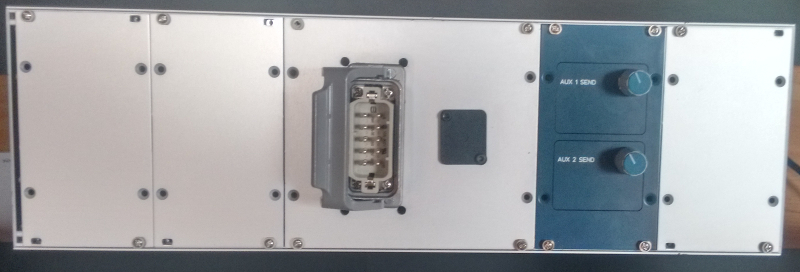
I've recntly finished a lunch box for a couple of Krässemaschine modules:

kmlbstuffed.jpg


kmlbback.jpg


This lunch box allows to record one or two signals without firing up the whole desk with 60+ tubes.
I had to install two pots as faders on the back. The panel is a leftover, the legend is wrong.
 
For future reference I have a design for a 24 way channel gain switch in 1 dB steps covering gains from 60dB to 27dB  and 40dB to 7dB with the 20dB pad engaged. Handy if you don't have room for a fader. It uses a regular ELMA 24 way switch. For neatness you can use one of the PCBs that attach to it to hold the resistors. The resistors are all standard E24 values.

Cheers

Ian
 
Back
Top