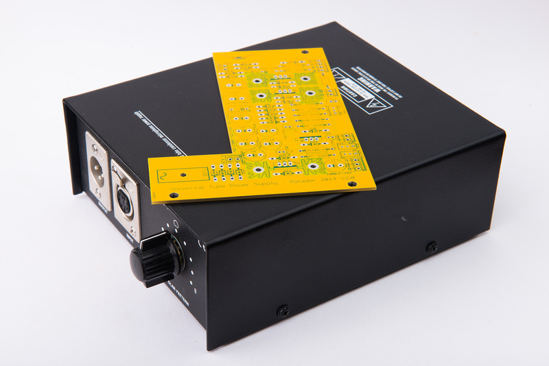
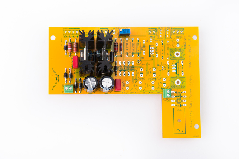
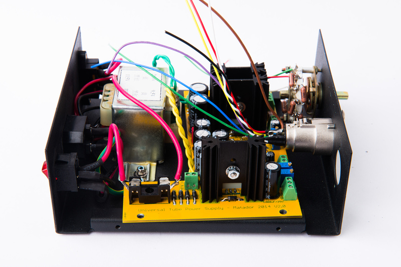
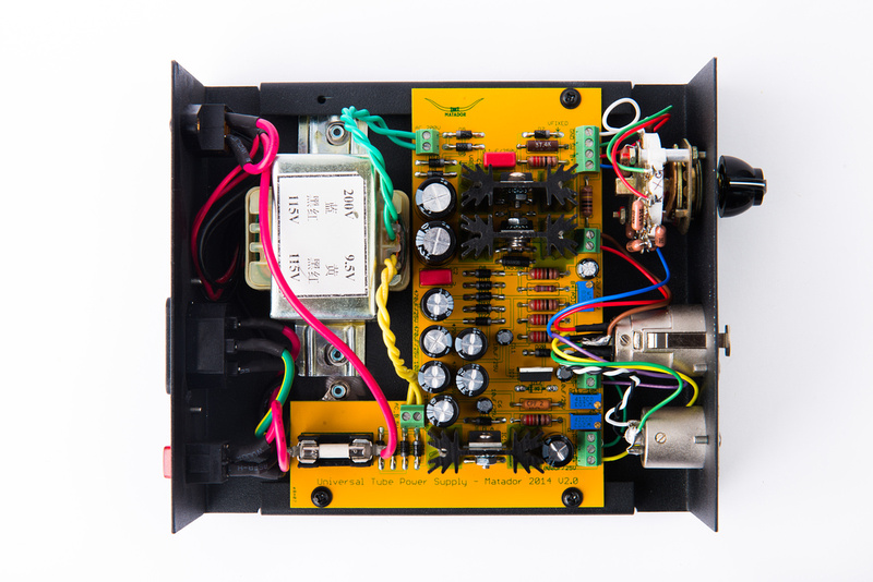
OK. . . matador still does not have a proper workspace set up, so it is incumbent upon me to attempt to prototype the 2nd revision prototype PCB. I am hoping I do not create too much smoke and fire! Matador has insisted I post photos for maximum entertainment value to the prototyping dollar. So, here we go.
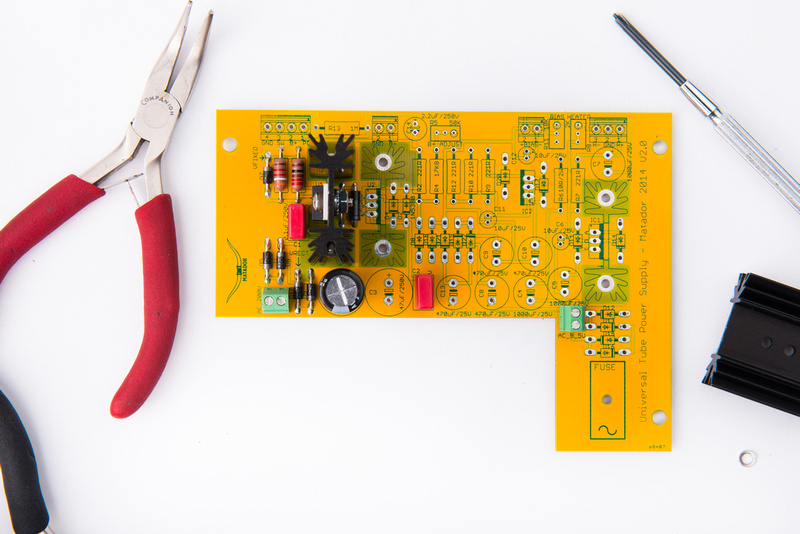
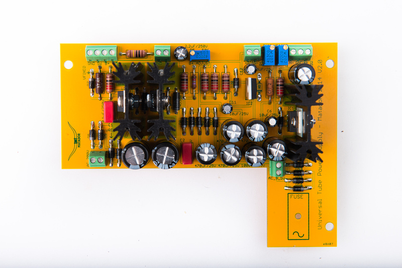
I was given a build sequence, so I begin with the first stage:
First Stage:
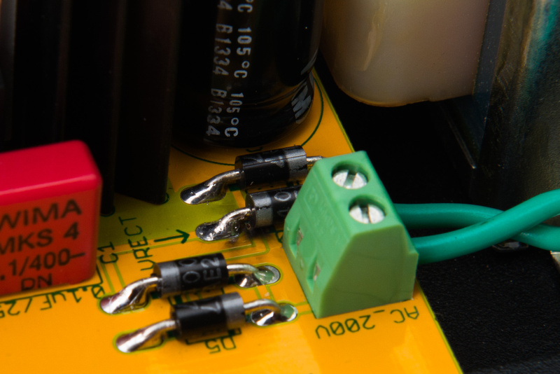
1) Stuff D3, D5, D6, D7, D9, D10 (1N4007)
2) Stuff D1 (1N5380)
3) Stuff R1 and R3
4) Stuff C15 and C1, C2
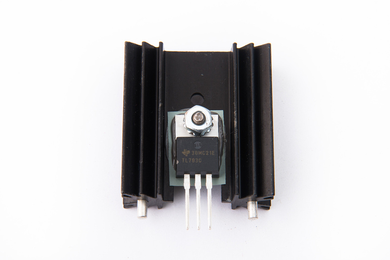
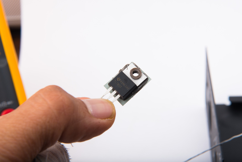
5) Stuff and heatsink U1
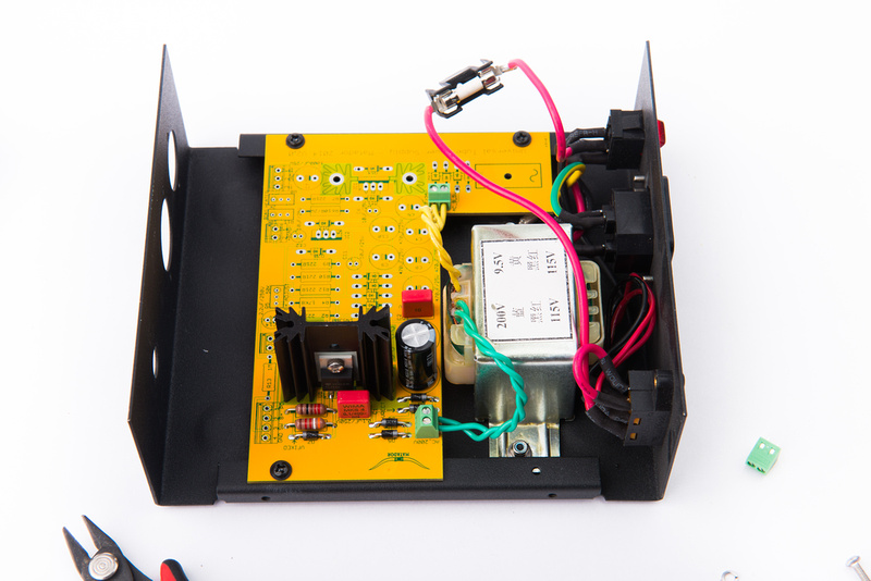
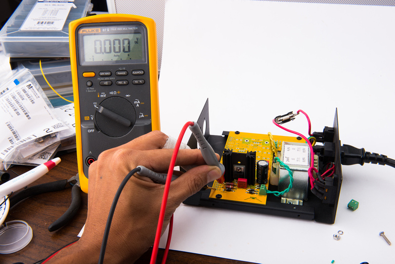
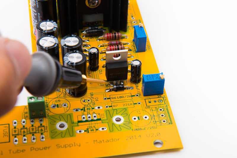
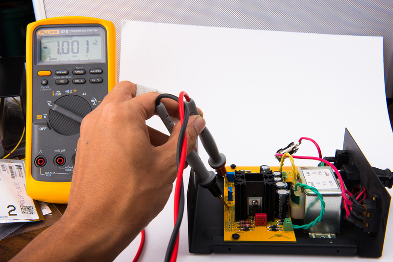
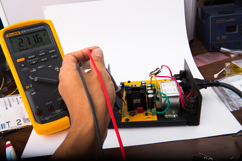
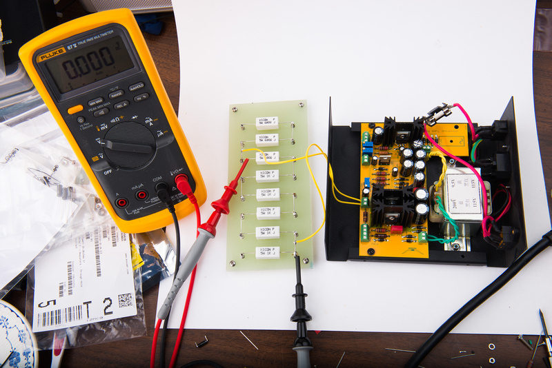
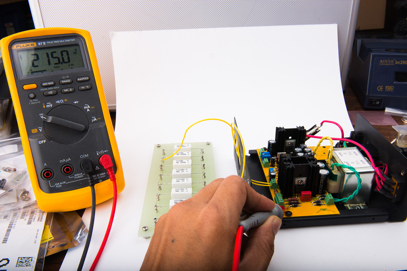
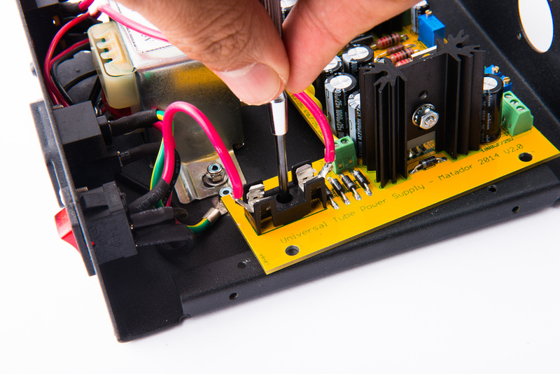
With the components for the first stage in place, I prepare to power up the board. Yes, the fuse is precariously hanging from the assembly, but I figured this board is going to go in and out of the case many times before I am finished, so I opt for a non-permanent solution.
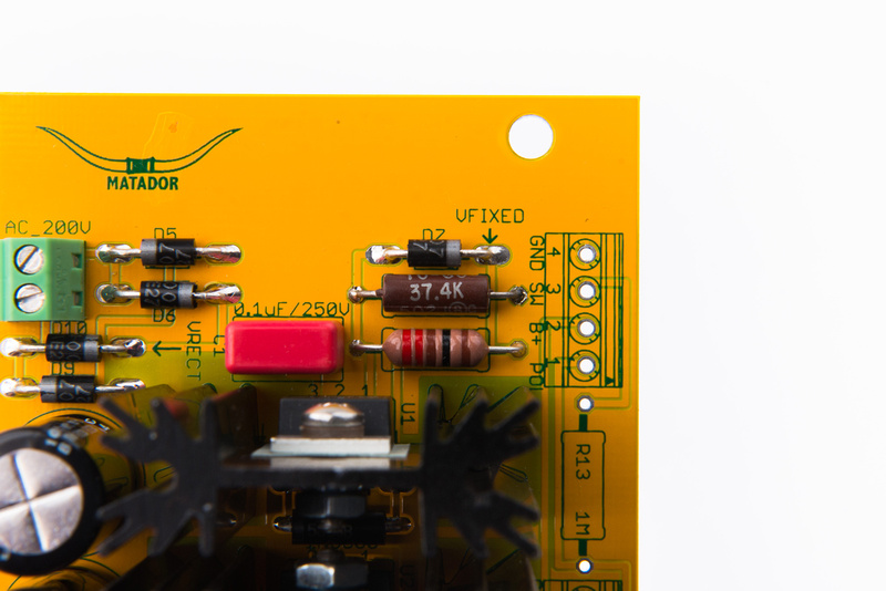
If all went well, I should see a fixed 225V +- 1% at the node labelled "VFIXED".
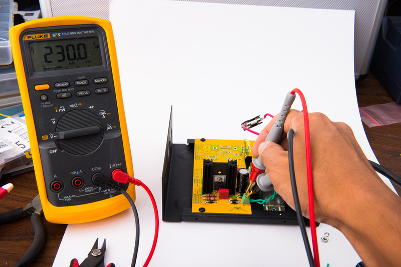
No smoke, but, all does not go well. . . in fact, I see nothing except directly at the transformer secondaries where I get 230V. . .. now that seems quite a bit out of spec

. Gotta love Chinese quality control!
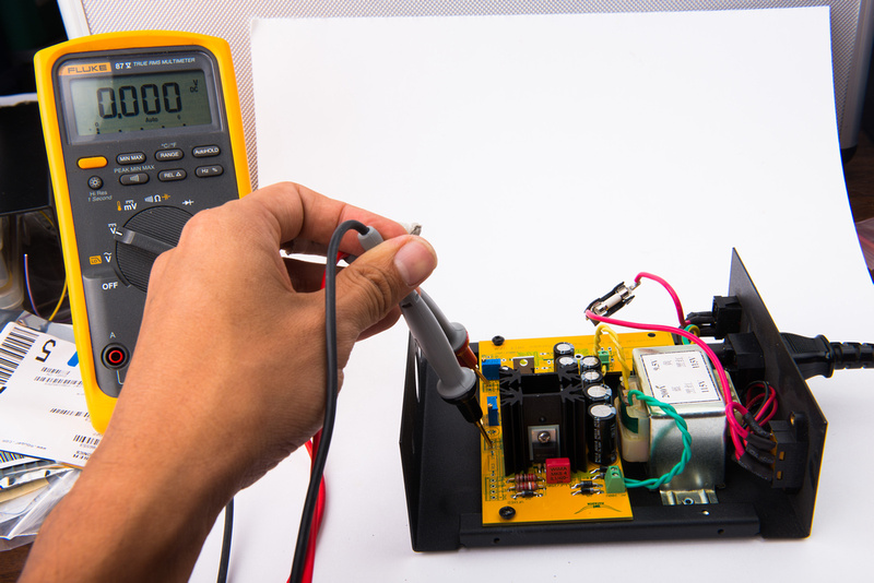
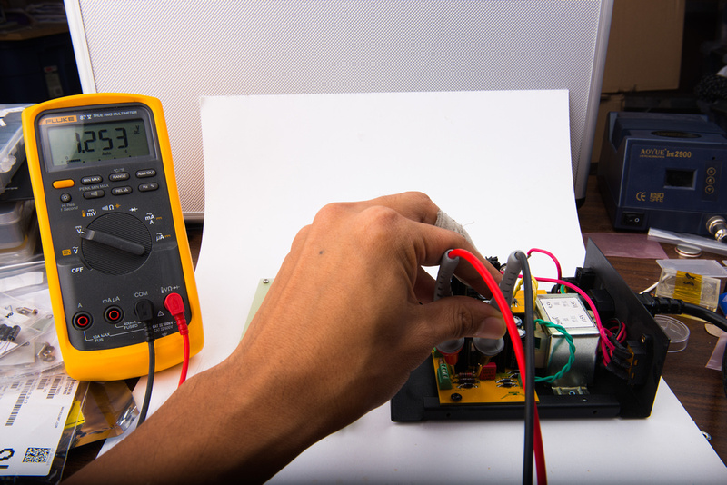
And here is my "VFIXED" voltage. . . or not voltage.
I scratch my head and wonder about it for a while. . . then, I call Matador and get voicemail. . . search the internet for full wave rectifier diagrams and trace the board. I probably should have asked for a schematic
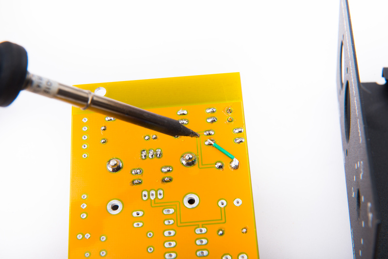
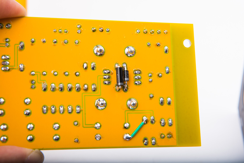
. It occurs to me I do not see a ground anywhere, so the circuit is incomplete. A text message from Matador confirms there was an error in the layout, and the schematic was not properly applied to the layout in software. Matador provides a fix which I implement with a piece of 22AWG wire.
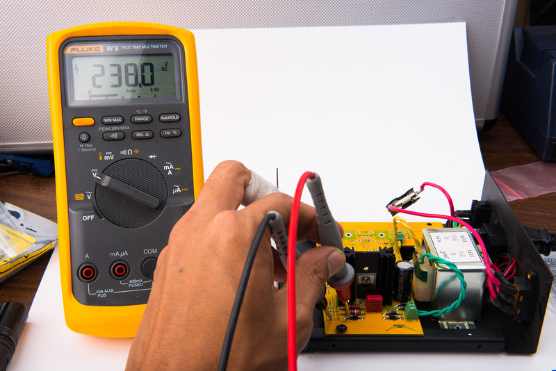
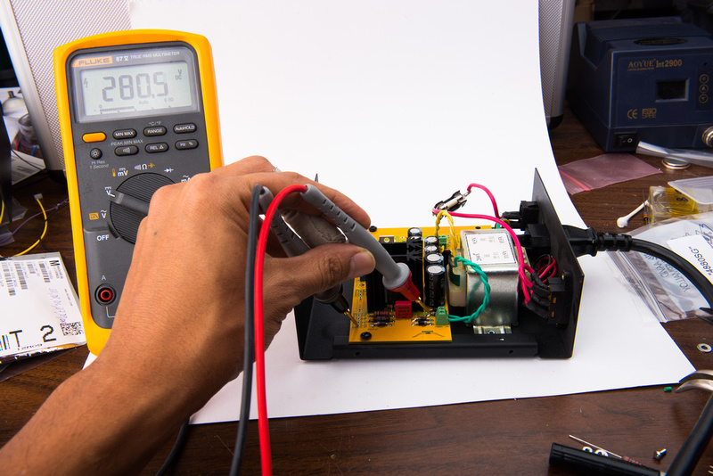
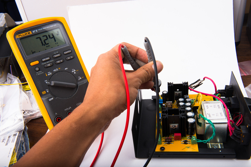
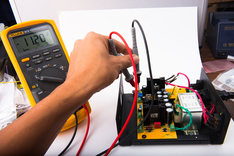
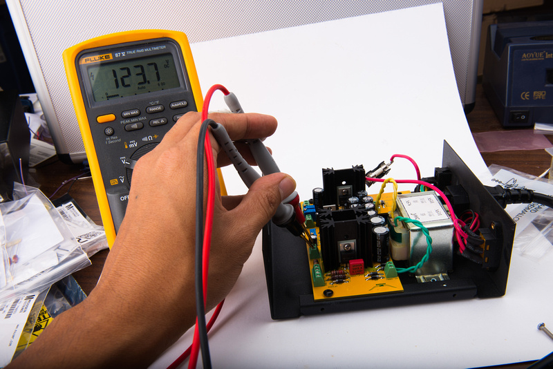
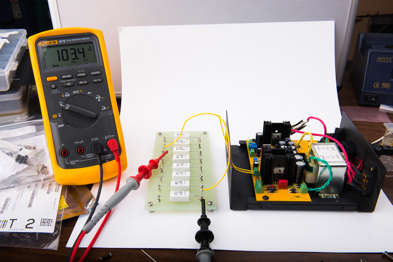
OK. . . now the first stage is alive! Still no smoke!
"VFIXED" sits at 238V. It should be 225V.
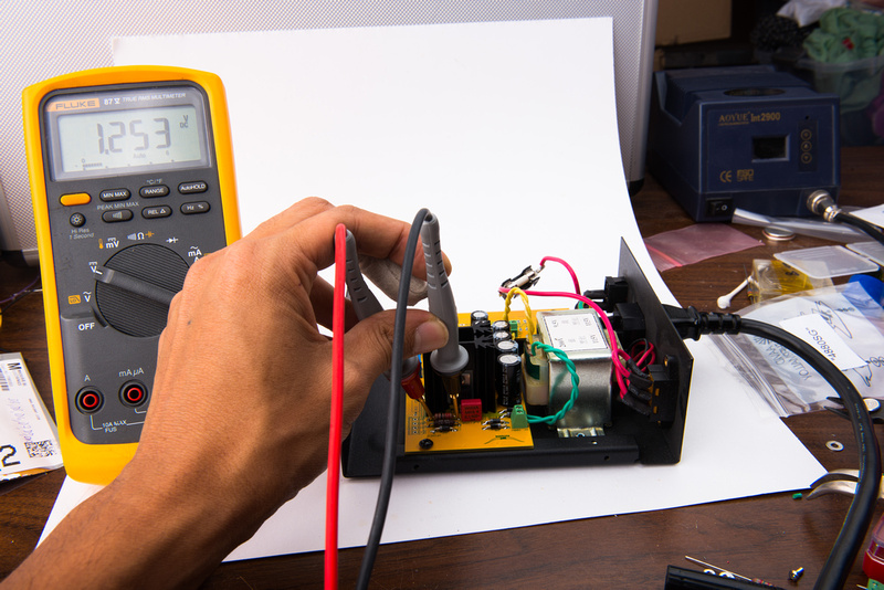
Voltage is not where it should be. My Vreg across R1 is 1.32V when it should be 1.25V. Not what we expected, but it will not blow up the 2nd stage, so I continue. In theory, without making a resistor change, this PSU will only be able to go to a minimum of 115V, so no U47 unless I make a correction.
Next, I populate the 2nd stage of the B+ circuit.
Second Stage:
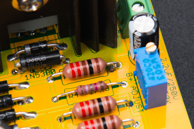
1) Stuff D4, D8 (1N4007)
2) Stuff D2 (1N5380)
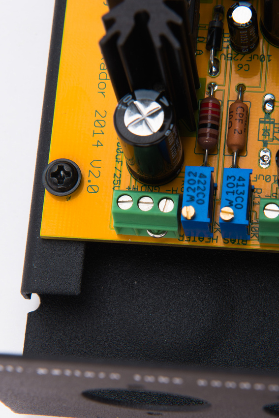
3) Stuff R2 and R4
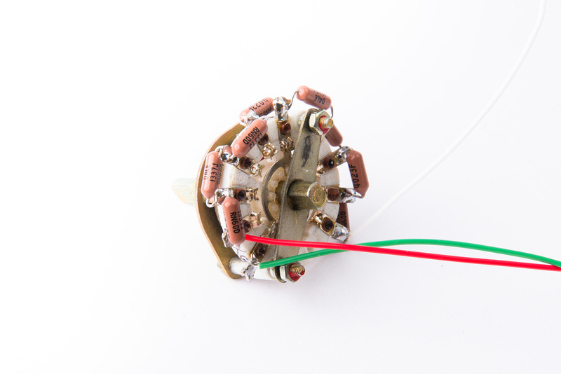
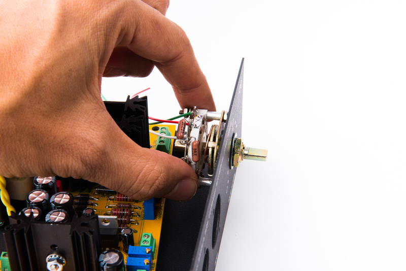
4) Stuff pot R5
5) Stuff C3
6) Stuff and heatsink U2
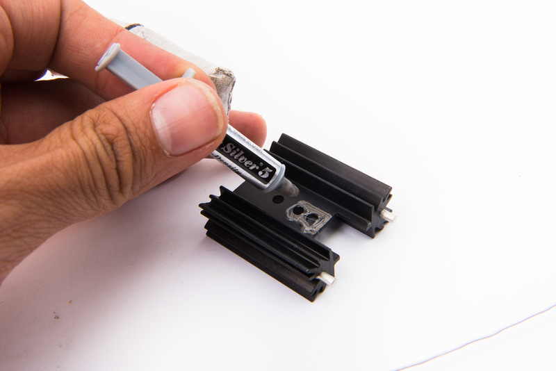
For the heatsink, I break out the thermal compound. . . i don't really anticipate trying to drop from 230V to 105V for U47 application in a fully enclosed, small case like this, but theoretically, this PSU should be able to do the job. If it does, this 2nd stage regulator will be called about to do the lions share of the regulation and it will get hot.
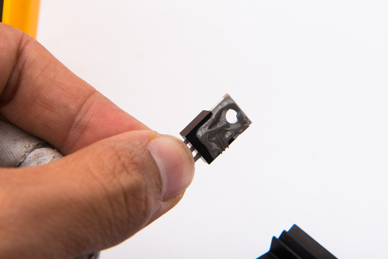
First some compound directly on the heatsink.
Then, some on the back of the regulator.
And we squish it all together with the insulating strip between.
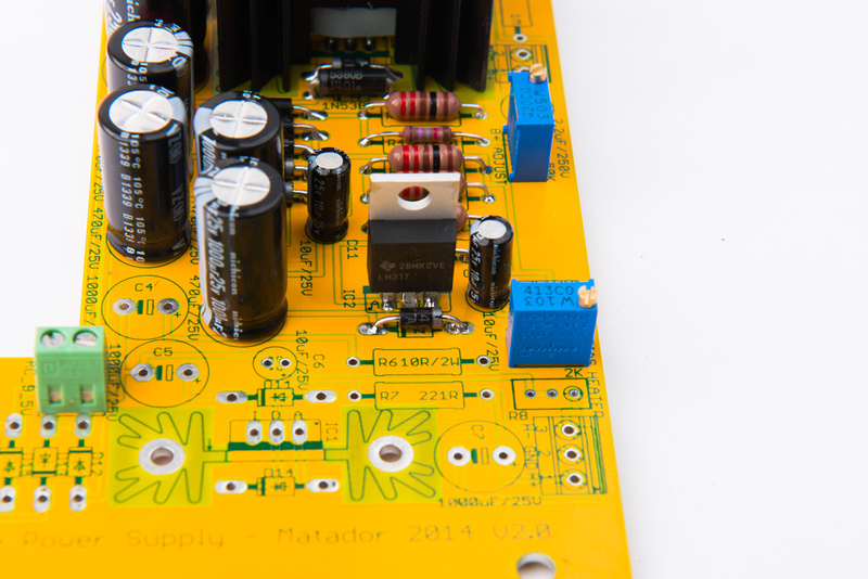
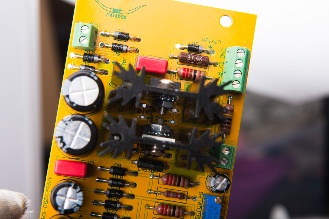
2nd stage populated!
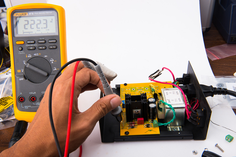
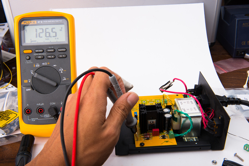
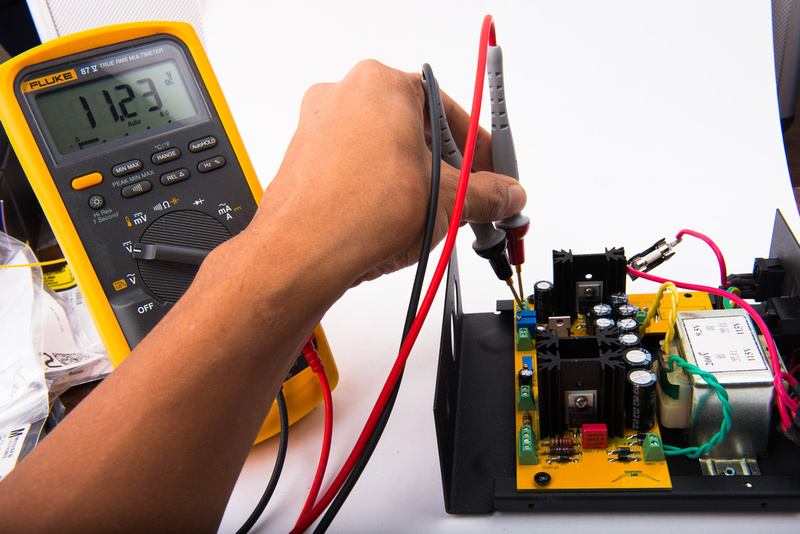
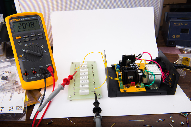
This is designed to give us 85V-220V range . . . and no smoke or flames. Let's see what we get.
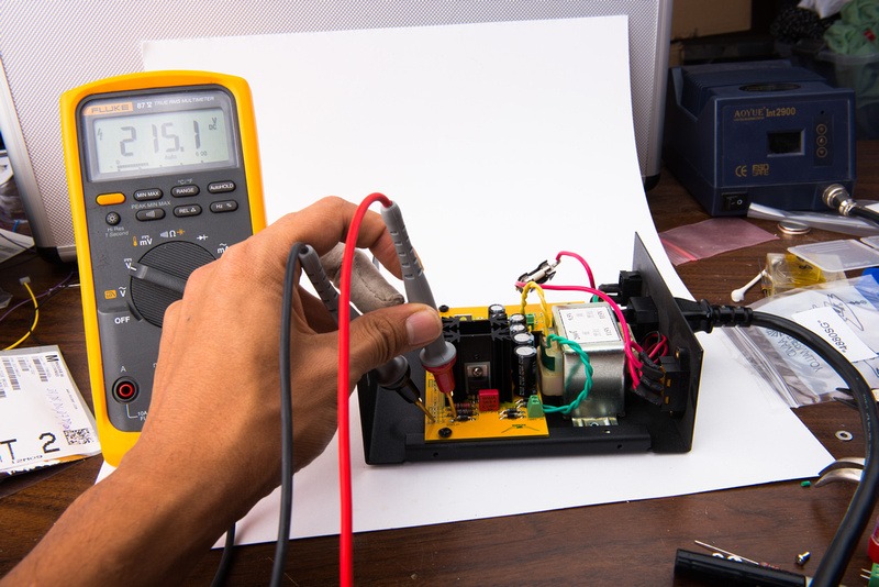
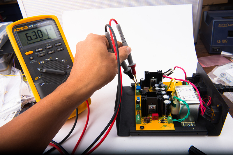
The high side looks fine at 222.3V.
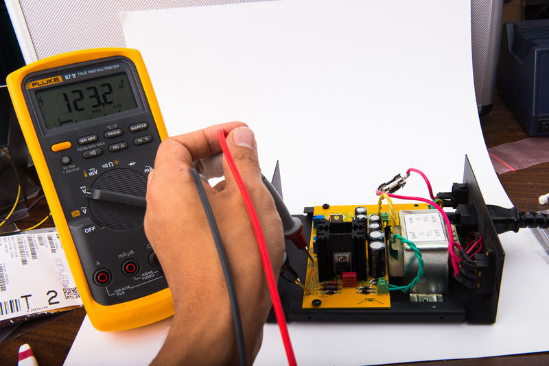
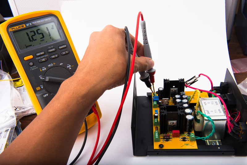
And, in this configuration, our supply bottoms out a 126.5V.
I figure it's pointless for me to stab and guess at resistor value changes for the 1st and/or second stage right now. We will not blow anything up component-wise, so I figure I will wait for Matador to wake up and read this post and then recommend alt values. For now, I continue to the fixed bias supply which is next in the chain.
Bias Supply
1) Stuff D18 through D22
2) Stuff R10 and R12
3) Stuff R11
4) Stuff C8 through C13
5) Stuff IC2
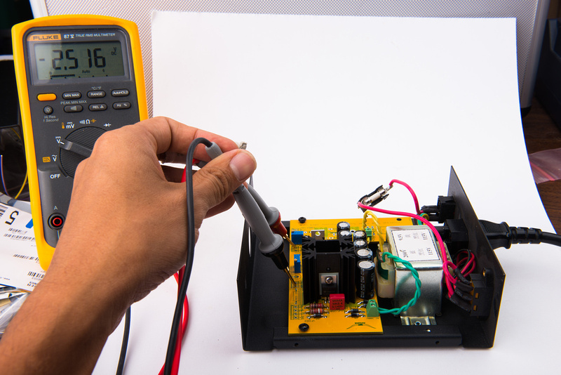
Measure BIAS+ - it should measure a fixed -2.5V (wrt. ground) regardless of the setting of R11
Measure BIAS- - it should measure between 0V and -2.5V (wrt. ground) by turning R11
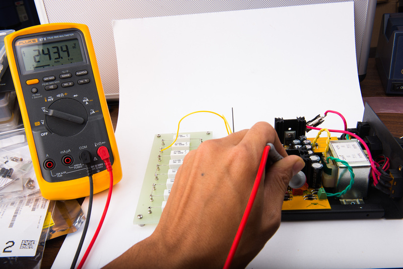
I do in fact get the expected -2.51V at BIAS+ and BIAS- allows adjustment between 0V and -2.51V!
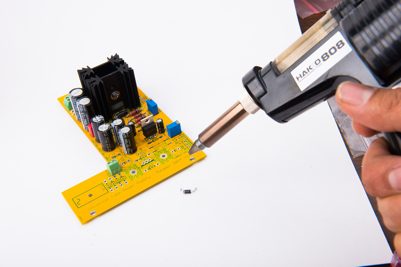
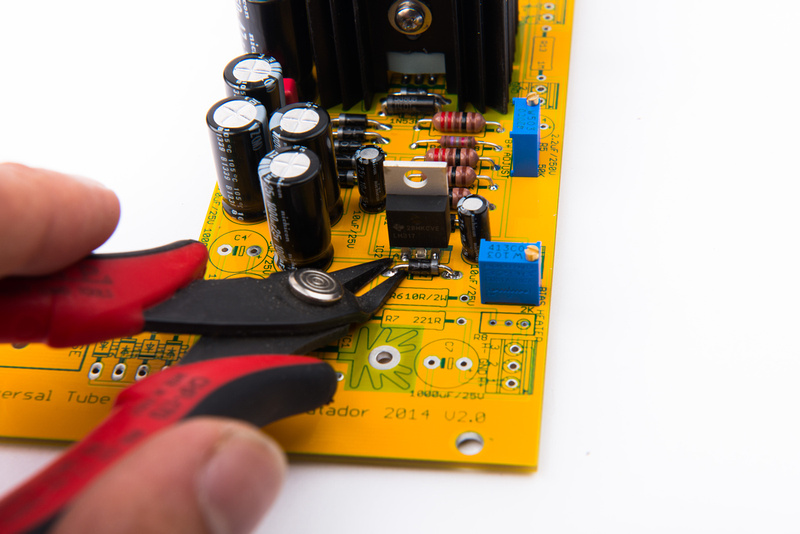
Next, I install D17. . . and poof! bias disappears. . .
In his notes, Matador indicated that he was not sure if the polarity was printed correctly for D17.
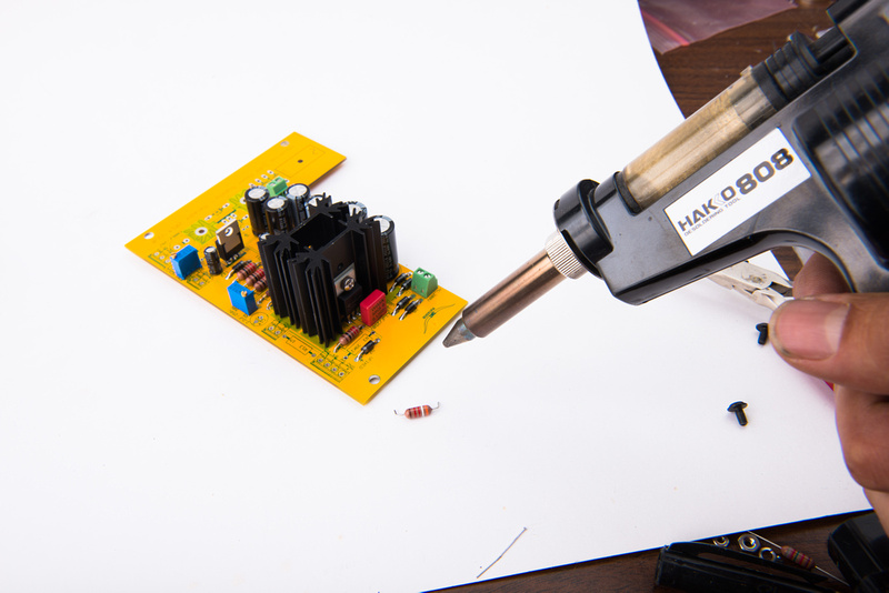
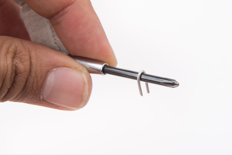
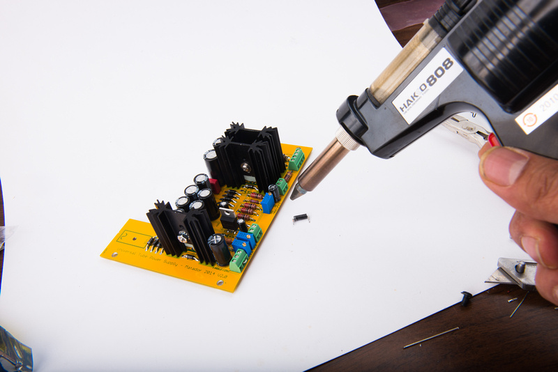
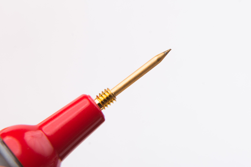
It seems like I use the Hakko 808 desoldering tool at least once on every project!
The 808 makes quick work of removing and flipping D17.
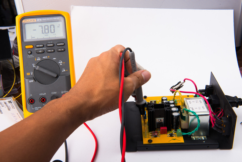
With D17 installed, I now get -7.8V at BIAS+ and on BIAS-, can adjust between -7.8V and 0V.
I set my bias to -1V since that seems a reasonable starting point and leave it there for now.
That's all 'til next time. Hopefully Matador can provide some alt values, and I can go to the local electronics store and pick up a couple resistors tomorrow and then continue.