trans4funks1
Well-known member
- Joined
- Feb 4, 2013
- Messages
- 328
Nice work!


Matador said:Thanks Chunger!
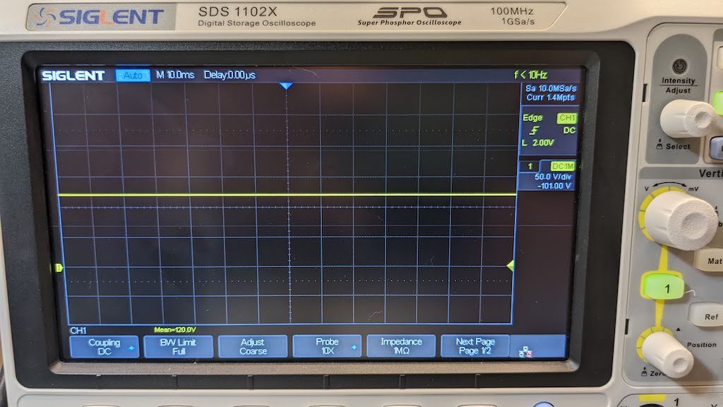
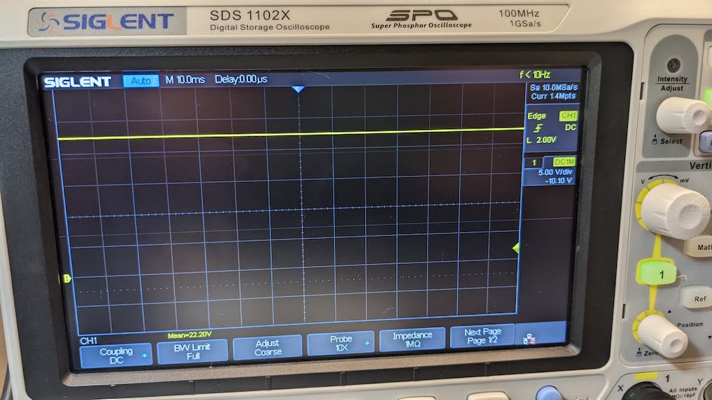
I suspect the buzz sound is 120Hz ripple: can you confirm this is the case on a scope?
I also suspect the problem is with minimum load current. Unlike the LM317T, the TL783C requires a much higher minimum load current to guarantee load regulation specs on the datasheet. If you draw less current, then the ripple rejection can go to sh*t. Tube mikes generally draw less than 1mA, so they don't guarantee the minimum load current by any means.
LM317T specifies 3.5mA typical, 12mA maximum. TL783C specifies only a maximum of 15mA. So a 221R voltage sense resistor on a LM317T guarantees a minimum of 5.6mA, so that is good for those designs. However I used the same value on this design with a TL783C, which isn't enough.
I changed the latest BOM to utilize 82.5R voltage set resistors, which provide a minimum load current of 15.2mA. I also added a final RC filter stage to the last regulated output, which degrades regulation slightly however adds another filter pole at 100R/47uF = 33.86Hz, which means that the filter is down an additional 12dB @ 120Hz.
Phrazemaster said:Hi, any updates on this project? I couldn't find the PCB in the store or white market. Or is this the PSU PCB that you are using for the C12 PCB kit?
Thanks; I am considering making an M49 but since my power supply fluctuates a lot where I live, I wanted a regulated design. This is regulated and would work for an M49, right? From what I could tell...
Thanks,
Mike
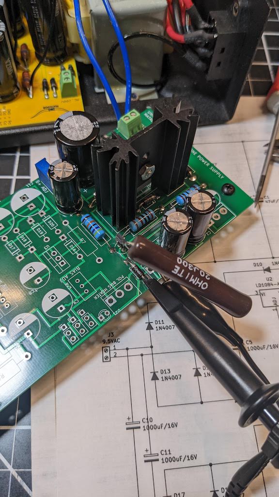
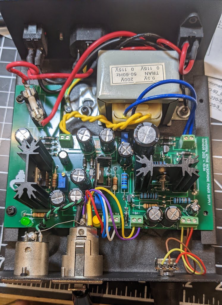
Brilliant! I need about 6 of these. Patiently waiting...Installed in the PSU case.
")


