FET847 Microphone Project Circuit By Jonathan Burtner PCB Layout By Poctop

GroupDIY Audio Forum

Help Support GroupDIY Audio Forum:

This site may earn a commission from merchant affiliate links, including eBay, Amazon, and others.
That cap bypasses the gate bias degenerative feedback portion with an HPF so the higher value pushes the HPF down in frequency causing less low frequency roll off and less phase issue around the corner frequency and above.

I believe the U87 uses a 20u cap in that position while the KM84 uses the 4.7u to prevent saturation in the OPT.

Cheers!
-jb
 
You should time the next turn to the same time with the chineese capsule group buy, and we could all build the ulitmate chineese diy mic!    8)

If the group buy is done, I'm in for 2 sets.
 
geebeeVIE said:
is there any way to increase the output level /gain of this circuit?

Not really, unless you feed it with some 68v or so. Thé km84 has à sensitivity of about 8mv/pa, same with à vintage u87. À modern mic run about 20 to 28mv/pa. Quiet à good step between. You need à good and clean premp to be able to run it clean, sincères you'll have to open up thw gain quiet more than à modern mic. It's à good time to drive your fav pre :)
 
Spencerleehorton said:
could you put up some comparison sample between the DU-87?

regards

Spence.

p.s. i still haven't built my 2 x FET847

Unfortunatly i sold my d-u87 so i can't do any comparaison. It's a wonderful microphone and highly customisable.
 
0dbfs said:
Deepdark said:
Dany's M7 capsule and cinemag cm5722

Very clean and tidy build and I hope you are enjoying it!

Cheers,
jb

Of course I do.

Little thing to take in consideration:

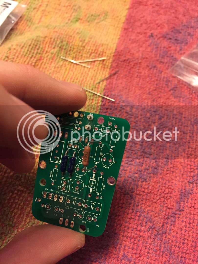
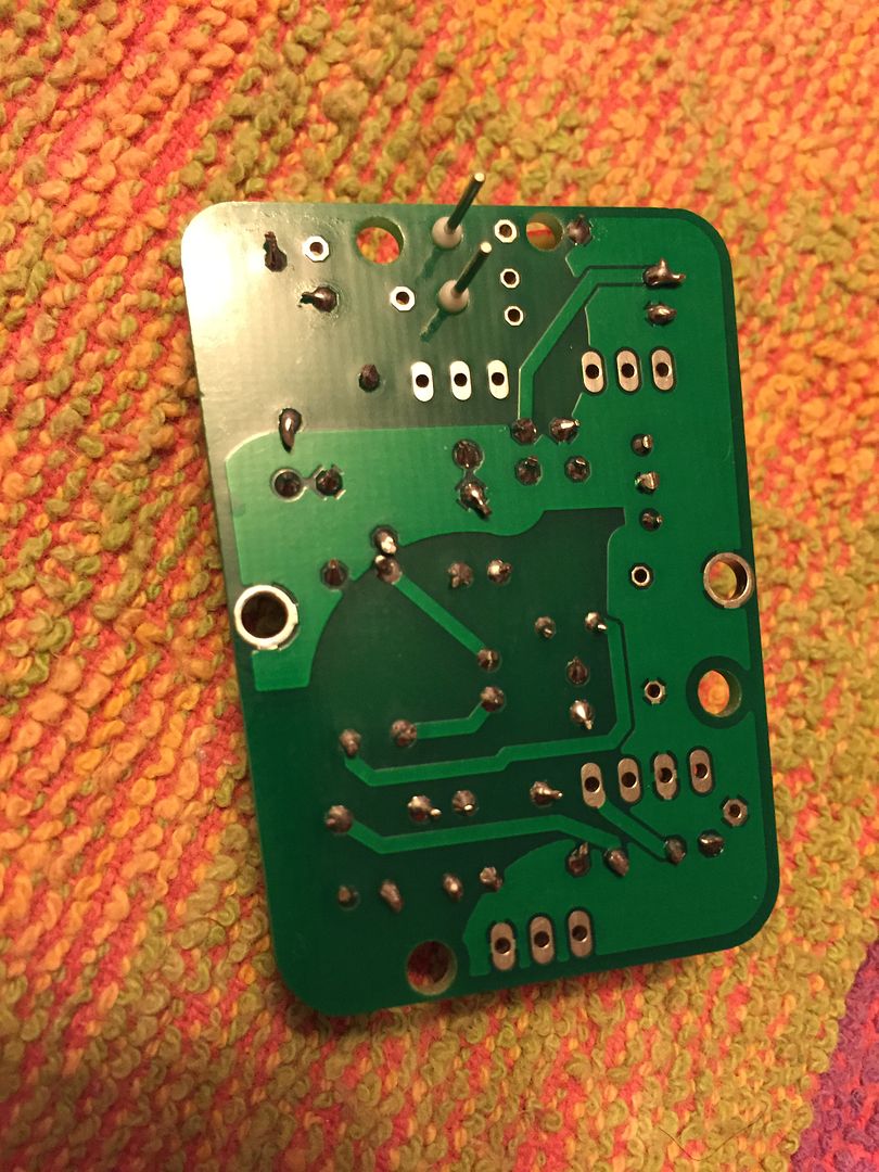
While mounting the Hi-z floating section, do not conect resistors and caps behind the board. If so, the leads are touching the pad and there is some leakage due to the hi-z and it causes a little hiss. I'll make a build manual so people will have a step by step guide of how to build this little bad boy :)
 
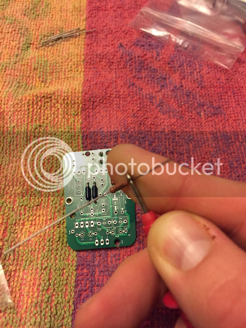
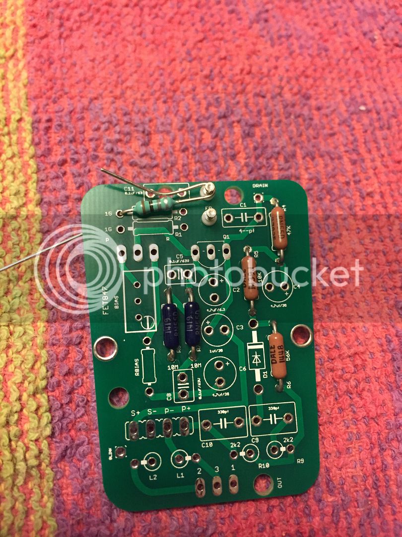
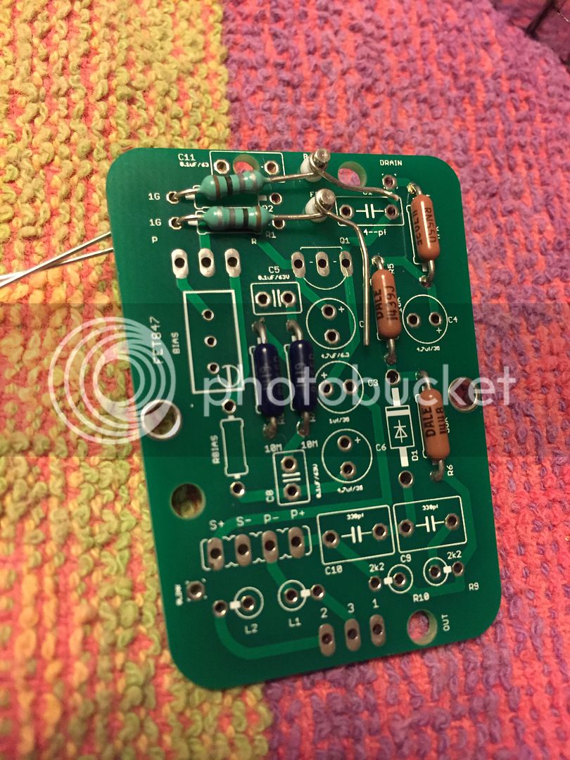
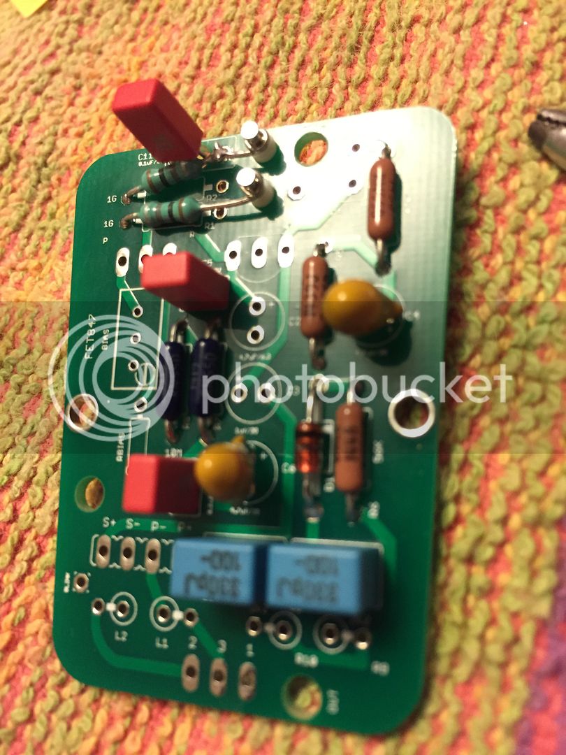
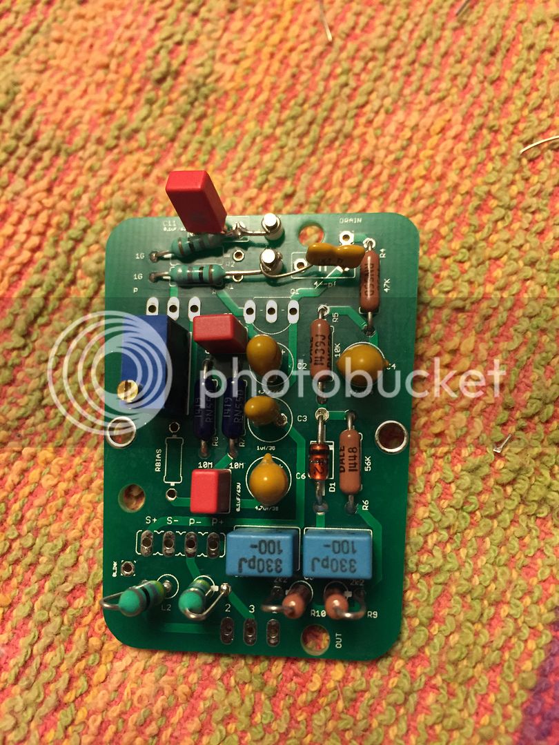
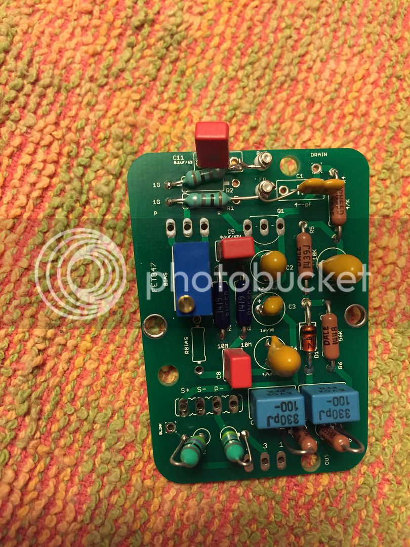
Best to install the Hi-Z side of those 1G's and the 0.1u film cap (or styro if that's what is preferred) directly to the teflon standoff. I did it on the front side of the PCB (cleaning off any flux) and everything was very quiet.

Cheers!
-jb
 
Glad to hear I did the hi Z resistors the right way on the front...  This is my first mic build, so I was a little confused in a couple places. 


2015-12-18%2020.00.52_zpsflucbk6o.jpg

2015-12-18%2020.02.26_zpsf89whv6a.jpg

2015-12-18%2020.12.37_zpszekk8n4k.jpg

2015-12-18%2020.14.31_zpsqh0nbnbg.jpg

2015-12-18%2020.32.42_zps26fibpms.jpg

2015-12-18%2021.00.41_zps3xm3rqiz.jpg

2015-12-18%2021.00.48_zpszvmjy2mv.jpg

2015-12-18%2021.01.07_zpswgnluavt.jpg
 
rockinrob86 said:
Glad to hear I did the hi Z resistors the right way on the front...  This is my first mic build, so I was a little confused in a couple places. 


2015-12-18%2020.00.52_zpsflucbk6o.jpg

2015-12-18%2020.02.26_zpsf89whv6a.jpg

2015-12-18%2020.12.37_zpszekk8n4k.jpg

2015-12-18%2020.14.31_zpsqh0nbnbg.jpg

2015-12-18%2020.32.42_zps26fibpms.jpg

2015-12-18%2021.00.41_zps3xm3rqiz.jpg

2015-12-18%2021.00.48_zpszvmjy2mv.jpg

2015-12-18%2021.01.07_zpswgnluavt.jpg

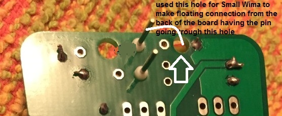
you could have actually used this hole to let the pin of the wima capacitor go to the other side of the board and make the floating connection form the back ,

58d028199487c.jpg


this is why I had made this hole available ,

just a thought,
D ;)
 
Back
Top