Great River MP-2 , info, schematics & discussions

GroupDIY Audio Forum

Help Support GroupDIY Audio Forum:

This site may earn a commission from merchant affiliate links, including eBay, Amazon, and others.
Hey guys!  Been gone from here for a long time, I hope everyone is still around and pulling some beautifully saturated sounds from their preamps?

I just ordered a pair of ac/dc's from jlm.  One will be set to +/-30V and 48V for this project, the other I think I will replace my crappy ptp psu in my calrec that didn't work ;)
I've  been re-reading this entire thread again as well as my own notes to jump start my brain on where I left off and I wanted to ask about the psu values..  I'm reading that some of your power supplies are over these values... the wiring diagram up at NRG's website (http://www.nrgrecording.de/temporary/MP2%20Wiring1.pdf) states he is feeding +/-30V and 60V.  I get that the  board rectifies down to +/-22V, but also recall Mr. Boboski (Hi Greg!) stating earlier in the thread you should feed the 48V section at least 50V?  Should I change my JLM PSU specs?

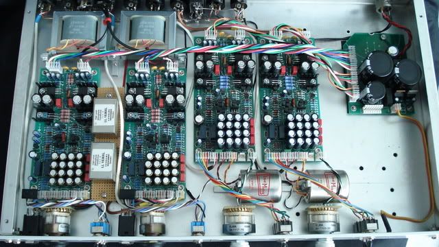
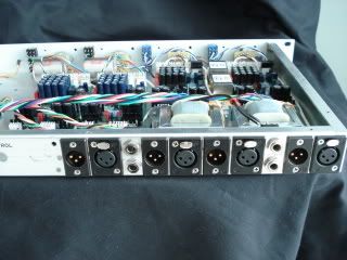
Other than that, I made some bracket/clamp out of hdpe to mount the input transformers sideways, made some brackets to mount the output transformers sideways as well, and cut a hole in the lid of my -too small- par metal case for the tranny's to poke their heads out of :)

Fully planning to finish this thing next week while I am on vacation, but I wanted to ask if anyone can help me out with a picture of the wiring on the output tranny?  The Cinemag group buy tranny's are what I have in there.

My last question is what site do you use for hosting pics now?  I let my website fall into oblivion, and I always like putting up pics of what I'm working on.
 
I'm not sure what the exact spec is but the regulators should be feed a couple volts over so they can regulate down
to the desired amount ,  this is the " raw " dc current filtered but not yet regulated [ on my board it's 63v down to 48 ]
which worried me at first,  but is apparently fine [ in use for years ] the preamp boards themselves have regulators for psu volts
so something over 24 is fine .
have been putting up with photo bucket ,
Picture069-1.jpg

Picture-2014.jpg

I should say  , I started off with a stereo pair , unbalanced out , and used it for years no problem [ 100' + runs ]
converted to a quad pre with output xfmrs on 2 channels and when comparing  [ by itself , either was fine ] the slight thickness was nice but didn't bother for output transformers on all four channels . The Mojo of the output transformer is nice but balanced in itself is not enough that you'd what to do it with an I.C.
 
Thank you to Dan Kennedy for releasing this project, and to okgb and everyone who participated in this thread - it's a wealth of information. I've been back and forth through it many times and am learning a lot. I'm finally getting this boxed up and, as I'm still a beginner, I have some beginner questions.

For the CMOQ-1H (http://cinemag.biz/output/CMOQ-1.pdf ),  following Test Circuit 4:
1) I short red to orange and blue to violet, do either of these go to ground? Is there a best practice for shorting these leads? I'm planning on soldering, twisting, applying cable ties and heatshrink tubing, then just letting it dangle.

For the CMMI-5C (http://cinemag.biz/mic_input/CMMI-5C.pdf ):
1) Looking at okgb's build picture (http://i83.photobucket.com/albums/j319/okgb/Picture069-1.jpg ) and comparing it to Dan Kennedy's (http://farm3.static.flickr.com/2471/3576891574_b12852c176_b.jpg ), it looks like you two are using different strategies for ground. It looks like okgb has shorted the transformer case to the case via mounting hardware (unless there's a nonconducting 4-40 stud and plastic washers involved), then tied the white (case) lead and black (inner shield) lead together. It doesn't look like they go back to the star ground but I can't really make out the details in that jpg. In Dan Kennedy's case it looks like the input transformer case is wrapped in tape and not shorted to the case except via the white and black wires, which are tied together and sent back to the star ground. Is this accurate?

For the ground, are these statements correct?
1. The only ground connection between the board and the star ground should be from pin 3 on J8.
2. Pin 1 on every xlr should go to the star ground and not to the board.
3. Each XLR case tab should also be connected to the star ground.
4. The power transformer's secondary center taps should be connected together and then to the psu ground, then the psu ground should be taken to the star ground. (edit: amveco 62075-p2s02 transformer: http://www.amveco.com/Miniature_Low_Profile_Transformers_2.htm )
 
Hello,

I'm making slow progress on this one.  This is my first build and I'm stuck on the switch.  For the last positions where there are two resistors on each contact do I just solder them together? or is there an easier way that I'm missing.  Also I'm not entirely sure which leads I use.  I think I understand the wiring diagram but there's 3 possible positions left open after all the resistors are on and I'm not sure which one goes where.  Thanks for the help!

Andrew
 
I can't find the actual schematic at home , though it should on the groupdiy gmail
but basically you could use a 2k pot , the switch simply selects different value resisters
to set the gain , two resisters maybe paralleled for a particular value  , you should see the
total values going up or down in either direction
 
AndTripp said:
Hello,

I'm making slow progress on this one.  This is my first build and I'm stuck on the switch.  For the last positions where there are two resistors on each contact do I just solder them together? or is there an easier way that I'm missing.  Also I'm not entirely sure which leads I use.  I think I understand the wiring diagram but there's 3 possible positions left open after all the resistors are on and I'm not sure which one goes where.  Thanks for the help!

Andrew

The last few resistors are wired in parallel, not in series. Each is connected to the appropriate tab on the elma. Next to each other, not end-to-end. I don't have a camera handy but later I'll try to post a picture of what I did. Once you've got the switch wired up you'll want to hook up your multimeter and check the values position by position to make sure you got it right.
 
In looking over this design, I'm wondering if the 2SK-389 couldn't be replaced by matching a load of similar JFET's with a similar circuit.

So Q5 is the constant current source, and it looks like it has 2 diode drops on it's base, so the constant current should be approximately two diode drops minus Q5's VBE divided by the parallel combination of R14 and R15 (221R || 100R would be 68R).  If I assume 0.75V for VBE then that's (1.4V - 0.75V)/68R ~ 1mA current through Q1 (split between the two sides).

So if I set up a test circuit with Q1 split into individual JFET's, and set R12 = R13 with precision resistors, and ground the gates of the two Q1 JFET's, I should be able to put in the "left" Q1, and sub in different "right" Q1's until the differential drain voltage between the two is near zero as possible.

I'm also thinking that the 2N3819 might be a good JFET sub for this circuit, as the VGS and IDSS parameters are similar to the original 2SK-389.

Thoughts?
 
Andrew, here's how I did the last few positions on the Elma with resistors in parallel. Anyone, please feel free to tell me if there's a better way.
 

Attachments

  • Elma-GreatRiver.JPG
    Elma-GreatRiver.JPG
    801.7 KB
From Dan Kennedy regarding the f.e.t.'s [ two posts above ]

Yep. Then when the matched FETs are installed try to physically
tie them together so their heating tracks.

from Greg- I've seen people use solder wick to couple transisters
 
Thanks Dan for confirming.  I had an error above, that should be 10mA constant current. ;)

I mocked up the first stage using 2N3819's and 2N3904 and 2N3906 parts I had laying around and got a good differential signal out of the drains...at least right before my signal generator went kaput for some reason.

Some of the transistors are no longer available, so I ordered 100 each of the following to test as replacements in my bread-board:

1) 2SK170BL - replacements for the input FET's...I'll find two that match for VGS and IDSS to use in the front end
2) MPSA06 (replaces MPS8099)
3) MPSA56 (replaces MPS8599) - these replacements have identical specs except for a slightly lower base-emitter breakdown voltage, and lower fmax.  The 8099 is 150MHz, the A06 is 50 MHz.

The 4401/4403 and MJE output transistors were easy to find.

By my somewhat casual inspection, it looks like the entire design boils down to one turbo charged discrete op-amp wired into a non-inverting gain fashion (feedback resistor to inverting terminal, and the adjustable gain resistor from inverting terminal to ground through the cap bank). 

I assume the intent with the 'super capacitor' was to get a pole in the feedback path as damn close to DC as possible, but having essentially unity gain a DC to keep the offset on the output as small as possible?

Also, it looks like gain range is between 8dB and 67dB.
 
While waiting for my transistors, I got this up and running on SPICE3.  I'm showing open-loop differential gain of about 1000 (or said another way, with feedback disconnected and inverting terminal grounded, about +24mV DC input on the non-inverting terminal causes the rail to just go to the +24V positive supply).  Wired as a gain of 2 I see about 0.09% THD into a 600ohm load at small signal level, rising to 0.3% when putting out 21dBu.  Very nice indeed!

I needed to tweak the compensation slightly to keep the simulation from oscillating at gain 2, but I figure I can tweak that better when I get my breadboard wired up to a real signal source.

I have a prototype layout complete for an entirely new board that's meant to fit inside one of Dan's (from Collective Cases) 9" 2U rack units.  The top half of the board has a +24V pour and the bottom half has a -24V pour, however the layout under and around the op-amp stages is relatively clear to keep parasitics to a minimum.  My board is designed for an external power supply so obviously the regulators are removed, and I've added a provision for a bank of output coupling capacitors in case I get into trouble with output offsets.  I currently have two channels of INA163 based preamps and two channels of Green's in this rack, so 4 MP-2's would be a great addition. ;)

Thanks again Dan for releasing such a terrific design to us DIY'ers.
 
Ok never mind:  I figured it out (I was missing the supply schematic).  R37 forms a voltage divider to drive the LED metering circuit.

Here's a PDF of my version of the schematic I've been working on.

Great River MP-2: Schematic

Right now I'm just trying to size up what a good PCB dimension is going to be.  I mostly use 2U racks so 2.5" is a good height, and if possible I'd like to squeeze down the length to around the 5" mark.  But I'll have to draw the rest of the circuit to see how much tweaking I'll have to do.

The only change I've made so far is to add a cap and resistor as part of the phantom supply.  It looks like on the original board, the phantom switch cut off voltage leading to the regulator.  Since my supplies are off board, I added a cap and bleeder resistor to add a soft start/stop to hopefully minimize popping.
 
And here is a VERY preliminary layout (at this point I'm probably just documenting this for myself, but in case anyone reading is interested):

grmp2-layout1.jpg


I switched all of the edge connectors over to my favorite Phoenix 3mm screw terminals.  I like these because you can stuff them while you mess around with prototypes, then when it's all done you can just solder to the holes left over. ;)  Plus they are cheap.

I haven't routed this board completely but it looks promising with only minimal trace density on the bottom to mess up the ground pour...the rats nest doesn't look too "ratsnesty".  I think I can get away with 15 mil traces for all wiring which should make the board cheap to manufacture.  The dimensions came out to 2.5" x 5.65", so I'm VERY close to my target of 5".  If I massage the heat sink areas a bit (perhaps switch to a vertical TO-220 with a vertical heat sink) I think I can get close.  I could always vertically mount the resistors but I find that it makes the board harder to stuff as the resistors always fall out when you flip the board to solder (plus it doesn't look as cool).

You can probably also notice that I only put mounting holes on the bottom, as I plan to vertically mount these.  However it would probably be wise to add some holes to the top in case I get bright ideas like trying to flat mount these into a 1U case.  I also think there's space along the right side to jockey things around and fit another three caps for the gain switch.
 
3nity said:
Count me in for 2 channels.
I was never able to get 2 channels when diypartssupply got them in stock

I was not planning on selling any boards, as this is not my design:  but if I make a few extra and Dan is ok with it I would be happy to sell off the extras at my cost to other GroupDIY'ers.  I missed out on the original sale too which is why I'm recreating a board in the first place. :(

Here is another try at a layout:

grmp2-layout2.jpg


My autorouter tells me that the board is routable, so that's a good sign.

I switched to vertical mount heatsinks for the output devices.  The Aavid 1.5" modules are nice because they have excellent thermal resistances.  If my math is right, if the ambient temperature is 40C, the output devices can sustain almost 10W each continuously (yes this is ridiculously over-designed on my part).
 
If you can do it , a 51x  ver. which could also be used as normal rack is a idea
that would be interesting , As it's a design no longer manufactured I think Dan is o.k.
with it  , although it would need to be designed for new fets , I could send you some of the old ones
 
Here is my final version, all routed.  I shaved it down to 5.5" and managed to route it with no vias:

grmp-2-layout4.jpg


I should be able to tack one or two on as riders to another panel within the next few weeks. ;)

I also added a few SMD pads to the bottom so I could break apart the first differential amp from the second, so I can better characterize the performance of the DOA stages.
 
Back
Top