Cool Stuff, makes it even more interesting!
You are using an out of date browser. It may not display this or other websites correctly.
You should upgrade or use an alternative browser.
You should upgrade or use an alternative browser.
Great River MP-2 , info, schematics & discussions
- Thread starter okgb
- Start date


Help Support GroupDIY Audio Forum:
This site may earn a commission from merchant affiliate
links, including eBay, Amazon, and others.
3nity
Well-known member
i might be in for 2 kits maybe, but 1 is for sure.
Thanks
Thanks
Matador
Well-known member
For those who have written me, I do not have this design completed yet.
Before I finish it, can someone (maybe okgb?) provide Dan's contact information via PM so I can get permission to release this?
Before I finish it, can someone (maybe okgb?) provide Dan's contact information via PM so I can get permission to release this?
okgb
Well-known member
I think Dan would say you've got an M1 now , nice work
[ Great River maybe busy with the A.E.S show but I'll alert Dan to the thread ]
Wasn't someone working on a 500 design for the 51x racks ?
[ Great River maybe busy with the A.E.S show but I'll alert Dan to the thread ]
Wasn't someone working on a 500 design for the 51x racks ?
I'd be interested in seeing the schematic and board layout, Matador.
Not sure what you mean about "breaking apart the opamp stages"?
The only thing I'd suggest about the Bourns pot idea would be to
include the pads for a fixed resistor to replace the pot, once the value
has been determined. That's why the two resistor positions were on
the original board, the circuit operates fine with the non-trimmed value,
but by tacking a pot for a quick trim you can find a standard value
to pull the slop in.
Maybe the fact that I've had most values of 1% resistors in my junk box for
20 years makes me a bit cavalier about this aspect of trimming, but for
the serious DIY'er, I would think it should be imperative. Even 5 or 10
each of the 5% values would probably get you there.
In general trim pots are evil.
Please carry on with the project, I'll support it.
Ptownkid
Well-known member
You're the man Dan!!! Thanks for taking the time to come look in on this.


rmaier
Well-known member
This is SO COOL. 8)
Matador
Well-known member
Dan Kennedy said:I'd be interested in seeing the schematic and board layout, Matador.
Not sure what you mean about "breaking apart the opamp stages"?
The only thing I'd suggest about the Bourns pot idea would be to
include the pads for a fixed resistor to replace the pot, once the value
has been determined. That's why the two resistor positions were on
the original board, the circuit operates fine with the non-trimmed value,
but by tacking a pot for a quick trim you can find a standard value
to pull the slop in.
Maybe the fact that I've had most values of 1% resistors in my junk box for
20 years makes me a bit cavalier about this aspect of trimming, but for
the serious DIY'er, I would think it should be imperative. Even 5 or 10
each of the 5% values would probably get you there.
In general trim pots are evil.
Please carry on with the project, I'll support it.
Thanks Dan, this is extremely generous!
To split the stages, I added a zero ohm resistor inline with the differential signal leading out of each stage. Thus I could observe the gain and response of each stage independently (a great aid for debugging!). Then I bridge the connections with solder when I'm done fiddling.
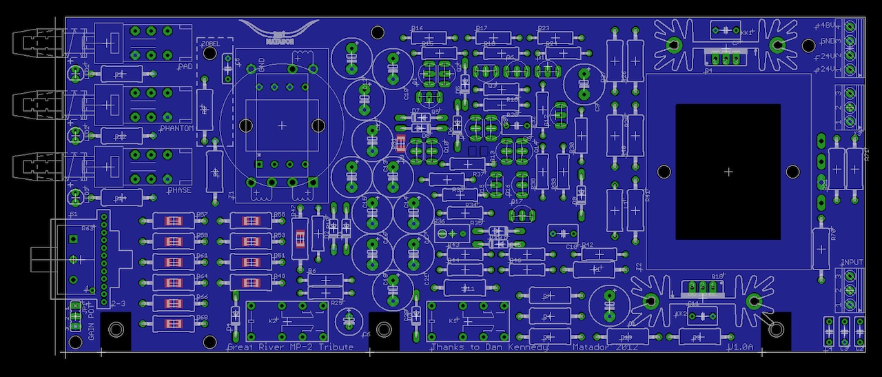
Here is the basic template I use for my own personal projects:
The input transformer is a combo layout for Cinemag, Ed Anderson, and Lundahl. There's also two holes if you want to zip-tie in some monstrosity and wire directly to the holes on the board (something I've done a few times!).
The gain set resistors are combo PTH and SMD (since it's far easier to find many values less than 10 ohms in SMD needed for the last group off steps).
I'll start laying this out this week.
Matador
Well-known member
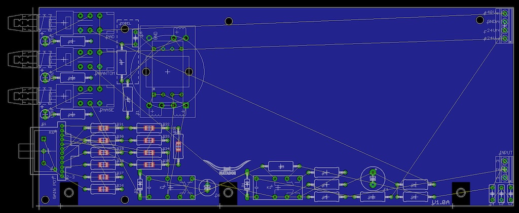
While I was eating lunch I threw together this preliminary layout. I'll need a glass of scotch and a few more hours to see if it is routable with reasonable design rules (there are a LOT of components on this design!):
On question from the original schematic: the output of the opamp is driven through a 10 ohm and a 20 ohm resistor going to two different pins on the "output" jack. I assume one is for the transformer, and one is for the direct output (and a third is for the meter driven through a 9K resistor).
Does the 10ohm feed the direct output and the 20 ohm feed the transformer?
Matador,
This layout looks awesome. How difficult would it be to add an OEP footprint to the input tx? I think the A262A3C would work. OEP is a great cost-effective option, and it might be interesting to hear this relatively colored tx with the clean circuit.
Dylan
This layout looks awesome. How difficult would it be to add an OEP footprint to the input tx? I think the A262A3C would work. OEP is a great cost-effective option, and it might be interesting to hear this relatively colored tx with the clean circuit.
Dylan
Matador
Well-known member
Dylan W said:Matador,
This layout looks awesome. How difficult would it be to add an OEP footprint to the input tx? I think the A262A3C would work. OEP is a great cost-effective option, and it might be interesting to hear this relatively colored tx with the clean circuit.
Dylan
If I remember correctly the OEP is very similar physically to the Lundahl, so it should be no problem.
A few other notes:
1) I will break the ground plane under the op-amp. Ground isn't used in the guts of the op-amp, and no ground plane should minimize clicks and pops when throwing the switches (the relays dump current spikes into ground).
2) The feedback resistor (the 2K7 from op-amp input to the inverting terminal) has no phase-lead compensation. I added a layout provision for one. Dan, did you find this wasn't necessary since you had internal "Miller" compensation (100ohm and 75pF)? Was it stable at low gains?
In my breadboarded version, I was getting squealing at low gains (high feedback) without one, but that was on a messy breadboard with tons of wires.
Matador
Well-known member
Just a quick FYI, the OEP A262A3C layout fits easily inside the others.
Done!
Done!
Ptownkid
Well-known member
WOuld it not be easeit to remove the power section and take that off board...
3nity
Well-known member
Matador can you post it actual size?
those reistors look pretty big to me.
I would do the switching without relays though...
+1 on the psu outboard too!
those reistors look pretty big to me.
I would do the switching without relays though...
+1 on the psu outboard too!
Matador
Well-known member
3nity said:Matador can you post it actual size?
those reistors look pretty big to me.
I would do the switching without relays though...
+1 on the psu outboard too!
1) There is no PSU on this board. The heatsinks are reserved space / stuffing options for the output transistors.
2) The resistor bodies are 3mmx9mm. This is standard size for Vishay RN60D 1/4W resistors. The larger ones are 6mm x
12mm for 1W+. Pretty much every 1/4W or 1/8W resistor I have purchased fits in these.
3) The actual board size is 3.25" high by 7.75" long. The pics posted so far are NOT actual size.
1:1 scale is a pain with exported images, so here is a PDF at 1:1 scale which looks about right.
http://www.musicalsparks.com/images/great_river/grmp2_template.pdf
okgb
Well-known member
How difficult would it be to add an OEP footprint to the input tx? I think the A262A3C would work. OEP is a great cost-effective option, and it might be interesting to hear this relatively colored tx with the clean circuit.
Dylan
Ptownkid
WOuld it not be easeit to remove the power section and take that off board...
I'm not sure an oep would be in the spirit of the pre ,Do anything you like, just don't call it a Great River MP-2 ,
[ Personally I think the Lundhal sounds great ]
if it's the onboard regulation you're refering to when you say power section , that's another one of those " Quality " features
[ Also a good feature to retain ] change enough things and better or worse it'll be a relative of the original
If you want the challenge though , design it for the 51x , and you can still use the same board for a 1RU , keep up the good work
Ptownkid
Well-known member
Well ok...it's a psu minus the rectification...
dmp
Well-known member
Guys! Come on.
He said:
Super cool project! Any possiblity to allow this to be used in a 51x rack? If the length of the board is short enough I could use it with the 51x edge connector")
He said:
1) There is no PSU on this board. The heatsinks are reserved space / stuffing options for the output transistors.
Super cool project! Any possiblity to allow this to be used in a 51x rack? If the length of the board is short enough I could use it with the 51x edge connector
Matador
Well-known member
If there is enough demand (and this board sounds fine and works) I would be happy to copy it to a 51X template. However keep in mind I don't have neither any 51X gear to confirm the design, nor capabilities to make or design front plates so someone else would have to do that.
Ptownkid
Well-known member
I can tag team that side of things with you.
Similar threads
- Replies
- 0
- Views
- 88
Latest posts
-
-
-
-
-

-
Modifying the Collins 356A Mic Pre for variable Negative Feedback Control
- Latest: abbey road d enfer
-