Great River MP-2 , info, schematics & discussions

GroupDIY Audio Forum

Help Support GroupDIY Audio Forum:

This site may earn a commission from merchant affiliate links, including eBay, Amazon, and others.
Well, I made the J8 pin mistake and was rewarded with a long ribbon of smoke out of Q13 on one of the boards. Fun! After fixing the J8 connector, the board passes signal, but it's slightly distorted. There's a layer of crackly distortion on top. The other board sounds fine. Next time I will triple check before applying voltages. Following the lead of Madriaanse way back in 2007 (!) I think I'll replace Q12/13.

EDIT: I wound up just replacing Q13. I went down to my local electronics store and found NTE123AP as a recommended replacement. I replaced the part, the crackle is gone and after measuring offset I'm almost done. After I replace R46 and label the front panel I'll finally be able to get down to using it.
 
Unfortunately I only had both channels working for 24 hours. The bad channel on which I replaced Q13 has had another component failure and I could use some help tracing it.

After replacing r46 I replaced the board and measured -21 V (not mV) for offset. I measured around, comparing various points between the good and bad boards and that -21V is in many places where it shouldn't be. For example, the 182 and 172 both have -21V at Emitter and Base, where on the good board they're around +/- 2.5. lm317 and 337 both measure fine.

I scratched my head while looking at the schematic for a while and thought that the problem might be with c34, 36 or 37, so I replaced those but there was no change. I know that I'm very late to the show on this one, but if anyone could offer suggestions for tracing the problem I would be very thankful.
 
Well, I'm at a loss. I've replaced q12 and q13 again and I'm reluctant to keep on desoldering because I'm starting to lift solder pads. q13 in particular is a bit brutalized on the pcb and I had to add little wire connections where the pads lifted. It's still no good - I'm showing -20V for the offset and no output whatsoever. If anyone has any ideas I would love to hear them.
 
I've got a call out to Dan , never know how busy he is , but it would be good to get you going
so , let's keep working on it , no worries , no hurry [ helps ] you will be rewarded !
 
Thanks so much for keeping tabs on this project. I ordered a full set of transistors and am wondering whether it would be good to replace all transistors. What else could have failed? the regulators seem to be putting out the proper voltage. Could the electrolytic caps rated for 50v have gone out and let through the negative voltage? I lack the knowledge to look at the schematic and trace where the -22v goes across the board, so i'm just thinking out loud here...
 
Success! I fixed it! I should have figured this out sooner, but the problem was with a lifted pad on R46. After replacing Q12-17 I finally thought to test the pads on R46. The leg that connects with R12 and R13 was in place but damaged. I soldered a piece of bare wire across the three adjacent pads and it now works.

The lesson for me is simple: slow down, take your time, ESPECIALLY when applying voltage and when desoldering. After lifting pads at a few places on the board I no longer have a pretty board, but I'm very pleased to say I have a functioning board. I'm attaching a picture of the brutalized part of the board.

Greg, thanks so much for sticking with me through this. Dan, if you read this, thanks so much for releasing this project to us. It has been a rewarding, educational experience for me.
 

Attachments

  • IMAG0026.jpg
    IMAG0026.jpg
    833.4 KB
Theres no more kits that are available unfortunately.
Not sure it was per Dan Kenedy request??
or was it the 990 out of stock per JH request??
 
Could see if Gustav wants to take it on , you'd been on your own for parts ,
The dual fet was obsoleted but don't recall if someone found a sub here
It's a little involved as a build , but worth it
 
3nity said:
Theres no more kits that are available unfortunately.
Not sure it was per Dan Kenedy request??
or was it the 990 out of stock per JH request??

Neither of those things are correct.

The MP-2 went out of stock as the last 6-10 kits sat on the shelf for 6 months...and the 990 is simply because the LM394 disappeared and the mat-12 would double the kit cost.
 
quote from Dan
" Gustav is welcome to make more boards. Frankly just about anything will
work, a pair of 2SK-170's is fine. " [ in regards to the dual fet ]

the gerbers were posted so for anyone , though Bryon had already established a run .

I won't give them up easily  but don't need , a couple of pcbs w/ smd resisters for the gain switch
a couple of the dual fets and allot of the inductors , swicth pcb's fit the greyhills that I have .
eventually for someone , regards
 
I have a new designed board that mates the guts of the MP-2 into a new preamp template, along with a few changes:

1) Switched the front end layout to accommodate 2SK-170 FET's
2) Switched all of the resistor trims to Bourne's 3296W style
3) Added layout provisions for either a potentiometer for gain, or a Grayhill 12-step gain switch
4) Added the ability to break apart the op-amp stages so that each can be individually trimmed for DC offset
5) Added standard phase / pad / phantom switches with LED's to the front panel that control relays

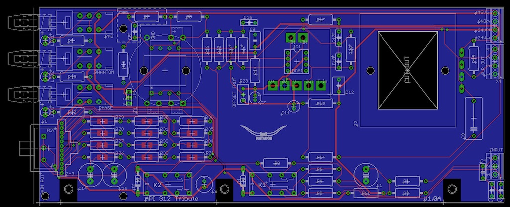
Here's an API312-style preamp in the same template, which measures 3.25" x 7.75".  I'm currently stacking these vertically in a 2U rack mount but they could probably be flat mounted in a 1U provided short standoffs are used.

api312_template.jpg


If Dan is ok with it, I would be happy to release the gerbers to GroupDIY once I finish up another project.  I'll tack a copy onto my next panel so I can check to make sure the layout is sound (or I can send it to somebody who wants to try it).
 

Latest posts

Back
Top