Great River MP-2 , info, schematics & discussions

GroupDIY Audio Forum

Help Support GroupDIY Audio Forum:

This site may earn a commission from merchant affiliate links, including eBay, Amazon, and others.
There is no info for the 500 here, it was just a brief mention a few pages back...the new board being discussed is a revisit of the original 1u version. However...you are right, a new thread is in order so as to not confuse the two boards.
 
Ptownkid said:
There is no info for the 500 here, it was just a brief mention a few pages back...the new board being discussed is a revisit of the original 1u version. However...you are right, a new thread is in order so as to not confuse the two boards.
Ok, my misconseption :)
I don't know what the practise is around here for new versions,
but yes, I could easily get confused ;)
 
I'm currently trying to determine the r46 value.
On my second MP-2 board r46 is 5.68K. I hope this is not too high because the trim pot should be only 2K as written in post 1?
The first board has some problems. With 2k in r46 i get 23mV offset. With 100k i get 11mV. Tried 300K but still had 11mV.
Should i go higher with the resistance or does this mean something is broken, maybe a FET is bad and should be switched out?
For the measurement i use a voltmeter on pin 1 and 2 of j7. I hope i'm doing this correctly?
I have nothing connected to the board just the psu no transformers, no switches.
Maybe I could switch some FETS between the boards for a quick solution?
 
If they're individual fets , you should use the method posted earlier [ not mine  ] for matching them
or try some new ones if dual , Dan says it sounds like they are too far out of balance
 
Thanks alot for asking Dan okgb! And thanks to Dan too of course :)
I was using the LSK389 which is the replacement part for the original 2SK-389.
Got lucky, someone here in germany is selling LSK389s on ebay so i bought three today.
I hope two of the three will be OK so I can switch out both LSK389s.
 
Those matched chips should be REALLY close.  I would look first at the matching between BJT's in the Wilson current mirror(s).  I would beta match both pairs to within 5% (easy with a DVM).

The first pair are P-channel BJT's (Q2 and Q3), and connect with the matched JFET pair.  The second set are N-channels (Q10 and Q11), and are part of the second differential stage.  If these stages aren't well matched (within reason) that can cause a circuit imbalance that is difficult to trim out.

Also, I would increase the value of R13 slightly.  R46 goes in parallel with R13, thus the combination of the two cannot be higher than R13 (49.9 ohms):  it can only be lower.  It may be your circuit wants a slightly higher value of R13, and the parallel combination cannot go higher even if R46 is infinite.  Try a 68 ohm for R13 along with a 2K pot (which gives a parallel resistance range of 0 to 68 ohms) and you may be able to trim it spot on.
 
Thanks alot for looking into this problem Matador.
Took me some time to think about your post.
I'm still not sure if I understood it.
I don't need to match both Wilson current mirrors to each other, it's about matching Q2 to Q3 and Q10 to Q11 right?
 
Man this thing is eating my lunch...I cannot seem to tame the power side from LM-337 my voltage is always -30+ no matter what I do...the LM 317 is ok...

And trying to bypass the regulators, going in with fully rectified power at 24 (+) (-) the resistor network R-30-34 starts smoking like a big dog...(I jumpered the rectifiers outputs with wire to a working psu that I can control the voltage on)

Its not like my transformer is huge either...

I have built Dans simplified psu (no rectification and no phantom)and it passes 30(-)(+)volts

I have gotten it to pass audio once or twice, at first it was incredibly distorted...

I have replaced Q-12-15...

Constant hum right now...smoke...

Q2-4 way to hot to touch...

These 20R 1W resistors are turning brown and smoking within 20 seconds of power up...

This with and without input, with and without direct, with and without input transformer and gain switch...

My gain switch Ohms out right on for each stage...I have the direct in tripping the correct way...(pins 2-3 shorted without input)...

This thing might end up on the black market soon...I am pulling my hair out...its almost impossible to get voltages since it starts smoking right away, I have physically checked all parts and the only thing I can think of is maybe the Q12-15 one of these is different orientation due to different manf.?????

The traces on this are very fragile so its a pain at times...no worries...just out of patience...

 
I bought some 2N4403 transistors and matched them using this technique for pnp transistors:
http://home.comcast.net/~ijfritz/projects/transmat001.pdf
I had a 0.5 mV mismatch on the old Q2 and Q3
I swapped them for 0.0mV mismatch.
This didn't do much, i still had the same offset.
So I did the 68ohm replacement for r13 you suggested.
I could trim it with the 2K pot to 226 ohm.
So is it OK if I put a resistor in and leave it like that?
Would be great i really like to finish it;)

@iomegaman don't give up! Unfortunately I can't help you but maybe you just need to put away and start fresh in a couple of days.
 
I will start a new thread shortly to keep the relevant information in a fixed place.

All I've had time to do is to populate the first differential section to confirm my matching rig was doing it's job.  I was able to trim the differential voltage down to below 5mV which is good news.  I've found at least 10 matched pairs out of a batch of 100 2SK170's (at least with my first pass).  I'll re-do a better schematic for the matching rig after all of the edits I had to make so people can roll their own.

Hopefully I'll have time to stuff and test the rest of the PCB this week:  it will be somewhat slow as this is a brand new layout and I need to confirm that everything is working properly stage by stage.  I'll document this process as well if there is any interest.
 
Matador said:
I will start a new thread shortly to keep the relevant information in a fixed place.

All I've had time to do is to populate the first differential section to confirm my matching rig was doing it's job.  I was able to trim the differential voltage down to below 5mV which is good news.  I've found at least 10 matched pairs out of a batch of 100 2SK170's (at least with my first pass).  I'll re-do a better schematic for the matching rig after all of the edits I had to make so people can roll their own.

Hopefully I'll have time to stuff and test the rest of the PCB this week:  it will be somewhat slow as this is a brand new layout and I need to confirm that everything is working properly stage by stage.  I'll document this process as well if there is any interest.
Did you ever start that other thread?  Any progress on this project?
 
Cinemag CMMI-5C:
okgb said:
Should be on the cinemag site , on the item page i think it is
either farther down or click on the different color word .
Worse comes to worse i'll open up mine

but basically wire the in 1:5 and the out is 1:1

the part that shows the testing circuit also has the wire colors

Brn /5 primary
red /2 primary

Org/8 secondary
Ylw / 11 secondary     
   
brn / Org for positive polarity to keep " in phase "

white is case , blk is inner shield , hope that helps
Thanks!
White and black: Does it matter what goes to primary or secondary? Guess not.
Are there any significant practical difference between the two?
 
J6, pad and reverse:

What's in and out?
In is connected, out is disconnected?

From this picture
http://i83.photobucket.com/albums/j319/okgb/Picture069-1.jpg
it looks like it's oposite
In is disconnected, out is connected.
??

Yet here
http://img86.imageshack.us/img86/1339/pict6178qv3.jpg
is in connected, out disconnected.
That's the most logical way to me, but I'm not so familiar with relays so..

Anyway, connected as last one, and I'll find out :)
 
Pad and phase are controlled by relays - schematic shows that when the relay is powered (switch on), the pad / phase is engaged.

White and black: Does it matter what goes to primary or secondary? Guess not.

white is case , blk is inner shield , hope that helps

Both white and black should go to a ground, chassis is best.
 
Dan Kennedy said:
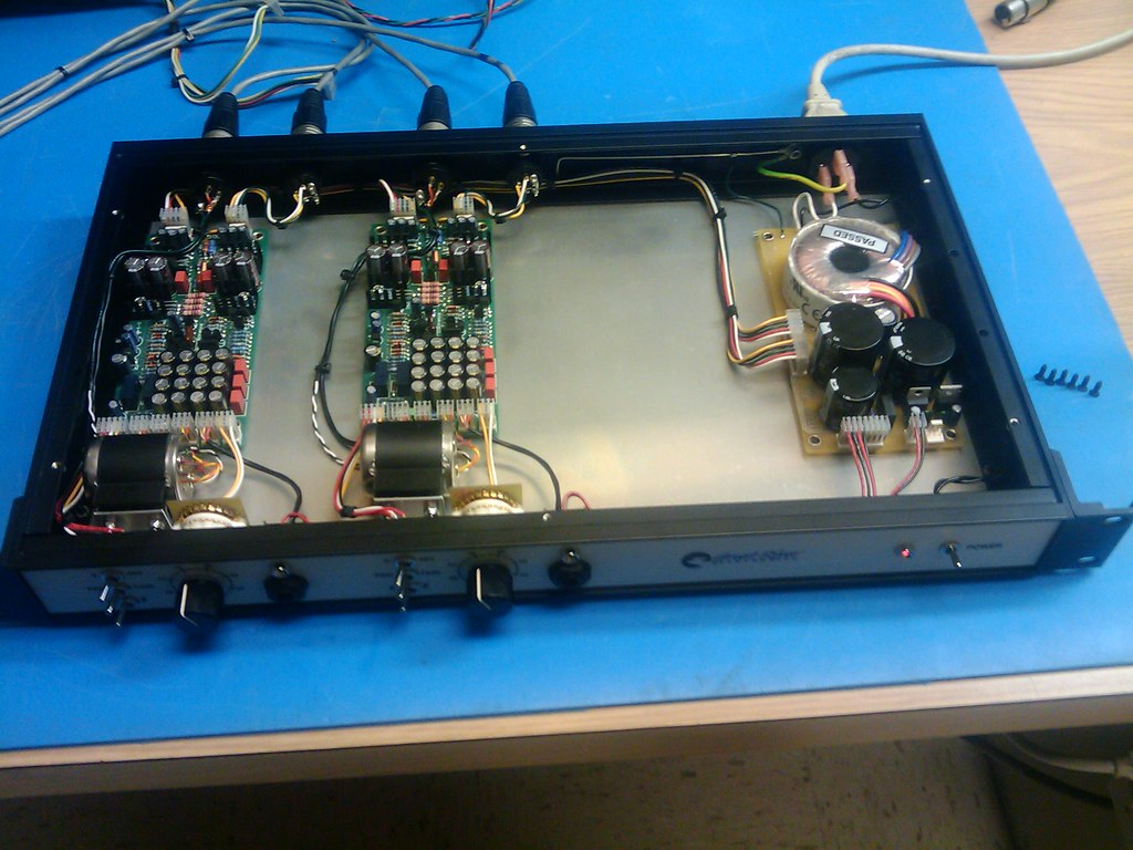
3576891574_b12852c176_b.jpg


I had to knock one of these old beast's off this week for a buddy, thought you might
get a kick out of one built from "scroungin's"
That's quite some neat wiring.
Thanks for sharing!
 
Back
Top