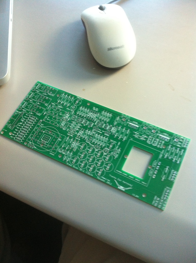
Great River MP-2 , info, schematics & discussions

GroupDIY Audio Forum

Help Support GroupDIY Audio Forum:

This site may earn a commission from merchant affiliate links, including eBay, Amazon, and others.
mistasanshou said:
Nothing to apologize for man, you're doing something awesome for all of us.  So can I go ahead and order my mp-2 case from Dan at collective cases?

My front panel layout is my own creation, and does not match any other pre-drilled panel.  If the case was meant to use panel-mounted controls (as opposed to PCB mounted), then yes you can make this work.  Otherwise you'll have to make your own front panel (like I did).
 
I will be able to supply different variations of custom front panels and cases. Will start mocking up the different configurations as soon as the boards hit my hands.
 
I did get a chance to mock up the matching circuit.  A few notes:

1) R5 and R6 must be made to be 1K to bring the drain voltages in line with the common mode input range of the OPA2277.
2) The measurement op-amp needs excellent bypassing.  My circuit oscillated in the 3MHz range, so we must bring the high frequency gain of the system within reason.  The solution:  0.1uF bypass caps right on the op-amps supply rails (pins four and eight), 0.1uF from op-amp output to the inverting input, and 0.1uF from the non-inverting input to ground.

Here is the data for the first 25 2SK170 devices I measured:

-0.192, -0.118, -0.199, -0.104, -0.112, -0.078, -0.233, -0.212, -0.319, -0.318, -0.119, -0.191, -0.192, -0.259, -0.296, -0.258, -0.117, -0.164, -0.091, -0.232

I took both devices that measure -0.192 and placed them in both differential positions.  The op-amp output read -19.4mV:  we are very close!  I trimmed R2 by placing a 100ohm resistor and a 1K pot in parallel, and dialed it until the op-amp output read 0mV average.  Both drains were sitting at 13.649V after trimming with both gates "grounded".

All in all it took about an hour, and most of the was just wiring up the breadboard.  The measurements took about 20 seconds per device.
 
Hello, I would like to start this project.
I start my bom, but there are some parts that I can't find.
-18UH / l1
-tbd-/ R46

I have another question.
Is it possible to use this power supply?
http://mnats.net/adjustable+phantom_power_supply.html

Thanks.
Sorry for my english.
 
I have allot of the inductors , free for postage  [ if that's worth it to you ]
R 46 to-be-determined  , check the first page for instructions on how measure the correct
value for this position . any psu that gets the boards +/- 24  [ a few above that for the regulators to work right ]
will do , and phantom for the mics as well .
 
As Matador suggested i got rid of the third bridge rectifier.
But the 6800uf elco on the negative side got really hot when i tried the PSU.
This is the new schema with the problematic elco in red:
FredPSU7.gif

The other one on the positiv and was cool. I measured +17,75 on the +18V output and something like -14V on the -18V output.
I later blew this elko when i tried to get rid of the current stored in the PSU after plugging the chord, which i did wrong. :eek:
I took the elko out of an power amp because my local electro store does not have 6800uf elcos.
Can i use 10000 µF 63 V instead which they have? This capacitor just takes the 60hz ripple out of the line and the bigger the smother the current gets correct?
Pls point me in the direction to find out why this elco got that hot. I'll swicht out the LM7918 and the elco.
How would you trace this problem, measure the resistance on the outputs or something? Propably a short on the negative rail?

 
The Frizzle said:
As Matador suggested i got rid of the third bridge rectifier.
But the 6800uf elco on the negative side got really hot when i tried the PSU.
This is the new schema with the problematic elco in red:
FredPSU7.gif

The other one on the positiv and was cool. I measured +17,75 on the +18V output and something like -14V on the -18V output.
I later blew this elko when i tried to get rid of the current stored in the PSU after plugging the chord, which i did wrong. :eek:
I took the elko out of an power amp because my local electro store does not have 6800uf elcos.
Can i use 10000 µF 63 V instead which they have? This capacitor just takes the 60hz ripple out of the line and the bigger the smother the current gets correct?
Pls point me in the direction to find out why this elco got that hot. I'll swicht out the LM7918 and the elco.
How would you trace this problem, measure the resistance on the outputs or something? Propably a short on the negative rail?

this schematic is correct, so the correct caps' directions are those on the schematic.
C9 would be much better 1uF instead 100nF.  10000uF 63V goes well, but 6800 uF should be preferred to reduce stress BR1.

The problem in this schematic that each reg keeps a around 12V of in-out voltage so they generate high heat.


Pardon my uninformed question here, but is this schematic showing 2 zener diodes as well as regular ones? Not sure of the conventions...and frankly there are about 2 different ways to read which way the current flows in sites online (although here it seems pretty consistent)...

I wish someone would just get rid of the 2 camps convectional vs...whatever, its the friggin 21st century for crying out loud can't we set a standard?
 
There are two back to back zener diodes shown on the input, right after the HiZ. This is commonly done to protect against voltage spikes. The 1n5248 is an 18v zener, so back to back they will shunt any voltage above or below ~18.6v, since a zener when forward biased has a standard voltage drop of ~0.6v. The zener voltage is the reverse biased voltage drop. The convention for diodes is that current flows from + to ground.
 
I'm psyched to build some of these!
Does anyone know if they can go up to 70 dB of gain, or is 60dB the max?
 
Not sure of the gain , but I can say with my original ones that I rarely need to go over half way on the gain  control
I believe Dan had said using them with ribbons was a consideration , so you're likely to hear room noise before
any preamp noise . whatever it is  , I think it'll be enough . depending on what ver. you make I could send you a
couple of the dual fets  [ I only have one or two left .
 
So how do regulators work and how much voltage drop is going to be too much?
The regulator can supply up to 1 Amp with adequate heat dissipation (from the datasheet).
Adequate heat dissipation is the key factor.
The regulator has to dissipate power dependent on the current draw and the voltage drop, P=VI.
So for example, if you are dropping 12v (~30v to 18v) and the circuit is drawing 0.25 A, the regulator needs to dissipate 3 Watts.
In a basic energy balance, the regulator temperature rises until it reaches equilibrium.
The regulator is thermally limited, meaning it will shut itself down if it gets too hot (125 C from the data sheet).
Now, it comes down to how much heat can dissipate from the regulator. For example, with a small TO-220 heatsink, from a Aavid Thermaloy 6021BG datasheet, at 60 C, the chart says it will dissipate about 4 watts.
The more current the circuit draws and the higher your unregulated voltage, the better heatsink needed.


Heya dmp,

thank you for your in depth explanation.
Problem is I don't know how much ampere the circut draws to solve that equation.
Maybe I'll just go for the 20v Toroid just to be sure.
Furthermore, I'm still not sure where to put the 0V from PSU.
Is it correct to put the ac power in ground on the star ground, plus the ground from the mp-2 boards, plus the 0v from the PSU?
And then also put the bus wire which connects all pin 1 of the xlr in and outputs also on the star ground?
Sorry for my noobishness, it's the first project I am finishing;)
 
You can use copper house wire to connect the xlr grounds and make this the star point
correct psu to there as well as preamp ground to there too .
 
It's hard to know what info is for 500 and what's for the original. Have you guys thought of a separate thread?
 

Latest posts

Back
Top