Great River MP-2 , info, schematics & discussions

GroupDIY Audio Forum

Help Support GroupDIY Audio Forum:

This site may earn a commission from merchant affiliate links, including eBay, Amazon, and others.
Hi,

on page 29 of this thread Josh mentioned a wiring diagram on the nrgrecording website(http://www.nrgrecording.de/temporary/MP2%20Wiring1.pdf), but the link is dead.
Does anyone still have this diagram? Please send it to me if you do.
And another question: I'm having trouble sourcing the output transformers in Europe.
Seems like i could directly buy them from jensen http://www.jensen-transformers.com/prices.html
The "JT-11-BMCF" would be the right one? I don't know what the "CF" stands for on page 1 of this thread OKGB wrote "Jensen JT-11-BM"
But if theres anyhow to get those or the Cinemag CMOQ-1H in europe would be nice not to hassle with customs.
 
you can save yourself some money and totally get by without the output transformer ,
it does add a little Mojo , but without comparing them side by side , most people would be
hard pressed to tell the difference , certainly you can get it going and add it later .

The Great River docs are in technical documents page here
 
Hi okgb,

thanks for you answer.
If I built without the Output Transformers I won't have balanced outs right?
I still have a leftover ssl 9k balance board, would this work to balance the ouputs?
Its dokumented here (last page) http://www.studio21.ch/diy/neeno/ssl9k/DIY_9k_Preamp.pdf
But this board would need 18V to power it up.
Could i add the 18V rail from the ssl 9k PSU http://www.studio21.ch/diy/neeno/ssl9k/DIY_9k_Preamp.pdf to sredna's PSU from page 23 which seems to be parts of the SSL 9k PSU anyway?
FredPSU.jpg

This would give me the 18V to power up the balance board.
The second BR1 is BR3 ;)

P.S. 2 any1 who reads this: please dont kill yourself by building this PSU it's just a question if it would work
 
Seems like a reasonable idea I might try myself , although I'm using my Quad Great river MP
with the Chamber Orchestra today , second pair with No output transformers , And I've never missed
them .

I use the the transformer  out on the main pair  , and the unbal out on the wide pair , I wired the box with both
xlr & 1/4 " outs  to have a choice , so I may still add the ssl 's outs with the THAT chips , just because I have the
jacks already there
 
You recorded a Chamber Orchestra today? Cool.
On which Instruments of the orchestra did you use your MP-2s?
I'll go with the no output transformer version like your second pair.
C3 C4 where wrong, they belong to the 48V rail.
Also I think the torroid connection needed to be inverted on the 18V rail.
I corrected that:
FredPSU2.gif

I'm still not sure if this is correct.
Someone whos not a electro mewbie like me pls approve that this is correct:)

 
The output of the middle bridge rectifier is more like 29V, not 24V.  Where is the 24V regulator?  Perhaps on the target board?

You also don't need the second bridge rectifier.  You can feed the rectified 29V directly (what is called J8 pin4 and pin2 below) into the bottom set of 7818's caps and inputs to derive the 18V rail from there.
 
I don't have any finished 9k's yet to tell you  , but considering it's transformer vs non  , I'd say
the mp is closer to a M1 than a 9k [ I heard from a reliable source  ]
I had done a shoot out recently with what I'd have thought should been very different pre's
and although the difference's were obvious they weren't as dramatic as to say any were not usable
as all of them sounded like good preamps .

I'll add to this post so as not to clog things up ,  I remember first listening to the mp's thinking they're o.k.
but not ' Totally amazing  "  but then what IS totally amazing and what does that  mean ?  if not that
I could not ascribe any bad qualities to them , there was nothing wrong , they simply did their job without
calling attention to something other than recording , and did not get in the way .
I think they have a " smooth  , solid "  mid range quality  and are my go to pre's for most things , I've never patched
them in and thought that I should try something else .  Being that there's allot of great preamps out these days , you
could probably say these things about other pres as well , so  gear , not usually the weakest link if you have to work
with whatever you have .
 
okgb said:
I don't have any finished 9k's yet to tell you  , but considering it's transformer vs non  , I'd say
the mp is closer to a M1 than a 9k [ I heard from a reliable source  ]
I had done a shoot out recently with what I'd have thought should been very different pre's
and although the difference's were obvious they weren't as dramatic as to say any were not usable
as all of them sounded like good preamps
Thanks!
Yes, I was thinking except for the transformers. Well, half finished Mp-2s on they're way to me. Looking forward to put all together and listen to them.
 
Sorry for the delay:  I am severely backed up on projects at the moment.  I did order the prototype panel, and I did redo a component list with a modern BOM.  I will send one of the prototypes to Ptownkid as soon as I receive it, as I'm not sure when I'll get a chance to stuff and test it.

As I said previously, the biggest change(s) from Dan's original:

1) No power supply regulation - the board assumes a +- and 48V supply is provided from another place
2) Front end JFET devices are converted to 2SK170BL.  They will have to be matched out-of-board and them trimmed for offset using the provisions of the original board
3) The layout features combo layouts for most typical DIY input and output transformers
4) I spent less board area on the "super-capacitor" - 12 devices in parallel
5) Combo layout for the gain section - options for a) a reverse log pot, b) a PCB mounted Grayhill, c) either SMD or PTH resistors for the gain adjustment

Sp just to be clear:  my board is *NOT* identical to Dan's original board.

 
Wish i had paid closer attention to the discussion...I would have said to just use the LSK389 which is what my last run of boards used. Still, matching a few FETS is a good DIY exercise.

I have practically all the parts for a few channels on hand so i can build and test rather promptly.

Cheers
 
Aye:  matching for IDSS and VGSoff takes about 1 minute per JFET.  I prototyped a small JFET input DOA using the same devices and was able to find 6 or 7 close matches in a bag of 25 parts.  I'm guessing a couple of the other pairs would have been "trimmable" in the MP-2 circuit as it uses more source degeneration that my separate DOA did.

A nice value-added service for you Ptownkid. ;)
 
Matador said:
Sorry for the delay:  I am severely backed up on projects at the moment.  I did order the prototype panel, and I did redo a component list with a modern BOM.  I will send one of the prototypes to Ptownkid as soon as I receive it, as I'm not sure when I'll get a chance to stuff and test it.

As I said previously, the biggest change(s) from Dan's original:

1) No power supply regulation - the board assumes a +- and 48V supply is provided from another place
2) Front end JFET devices are converted to 2SK170BL.  They will have to be matched out-of-board and them trimmed for offset using the provisions of the original board
3) The layout features combo layouts for most typical DIY input and output transformers
4) I spent less board area on the "super-capacitor" - 12 devices in parallel
5) Combo layout for the gain section - options for a) a reverse log pot, b) a PCB mounted Grayhill, c) either SMD or PTH resistors for the gain adjustment

Sp just to be clear:  my board is *NOT* identical to Dan's original board.
Nothing to apologize for man, you're doing something awesome for all of us.  So can I go ahead and order my mp-2 case from Dan at collective cases?
 
I thought I would document the matching process for those that are interested (and for myself to refer to).

It's best to match the devices in a similar operational configuration as they will be used.  What better than to use the circuit itself as the matcher!

jfet_matcher.jpg


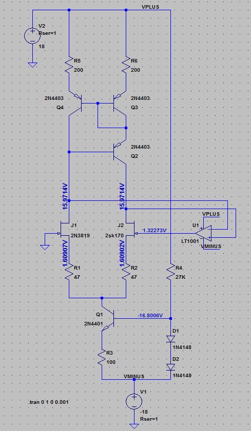
So in the MP-2, the front end is set up with current mirrors.  A constant current is set up through Q1, being equal to roughly 5mA (or two diode drops - VBE divided by R3).  In a perfect world, with both JFET's gates grounded and everything else within reason, we should see each JFET passing half of this current equally under similar bias conditions.  This only happens if both JFET's are exactly the same.

So the circuit above uses an op-amp to force this to happen.  The difference in drain voltages is sensed, and then the op-amp makes it's output whatever it needs to be in order to make this true.  In the picture above, I've forced a horrendous pairing by placing an SK170 in one side and a 2N3819 in the other.  What you can see is that the op-amp has to apply 1.32V on it's output in order to make the drain voltages the same.  This means that the SK170 passes 2.5mA with 1.61 - 1.32 = 0.29 or -0.29 VGS, and the 2N3819 passes the same 2.5mA with -1.61V!  This would make a bad differential pair as there would be significant offset being amplified by the rest of the follow-on circuitry.

However what we can do is hang a multimeter on the op-amp's output, and substitute in various SK170 devices and then note down the correction that the op-amp is applying to balance the circuit.  If we can find two devices that measure the same corrective offset, then we have a matched pair.  If we then place those two devices in the differential positions, the op-amp should be essentially try to drive "ground" (or 0V) in order bring the circuit into equilibrium.

Once two devices are found that are close, we can use Dan's original trick of "source degeneration" to bring them to an exact match.  On the layout, R2 includes a trim pot which goes parallel to a fixed resistance.  Of we use a 100ohm fixed resistor in parallel with a 1K ohm trim pot, we can dial in the effective R2 anywhere in-between 0ohms and 91ohms.  We can tweak this value until the op-amp reads exactly 0V and we have a good match.

A high-precision / low-offset op-amp must be used:  I have a stash of OPA2277PA devices that specify offsets in the 20-50uV range.  Due to the tremendous open loop gain of this preamp, the matching must be well done in order to keep the output from sitting significantly away from 0VDC, as no coupling capacitor is used.  Once the preamp is built, one must again go back and revisit the trimming of R2 to make sure that the output sits at 0V with both JFET inputs grounded.  And of course we have feedback to help correct this as well.

Another word to those trying this:  run open loop, the temperature of the devices will impact the matching.  The circuit needs to "come up to temperature", and should be similar to that inside whatever case you'll be using.  I can imagine that even breathing on the test rig will cause the voltages to shift around.
 
Back
Top