You are using an out of date browser. It may not display this or other websites correctly.
You should upgrade or use an alternative browser.
You should upgrade or use an alternative browser.
GROUP BUY: Universal Audio 176 - a 100% faithful recreation of a legend! CLOSED!
- Thread starter rainton
- Start date


Help Support GroupDIY Audio Forum:
This site may earn a commission from merchant affiliate
links, including eBay, Amazon, and others.
Phrazemaster
Well-known member
Hi Martin, if you were to drill holes to fit the Davens, would they be hidden behind the knobs? I can't tell from pictures. If so, it might be nice to have the holes for Davens pre-drilled and countersunk, if they won't be visible no matter what the user chooses.
I got myself a pair of Mallory t-pads for a good price on the bay, so I'm stocking up parts!
Great, great work man!
Mike
I got myself a pair of Mallory t-pads for a good price on the bay, so I'm stocking up parts!
Great, great work man!
Mike
Phrazemaster
Well-known member
Yes! You can find them on eBay NOS very easily right now!ilfungo said:Hi Phrazemaster
the Mallory t-pads you have hare 600 ohm?
Thanks!
rainton
Well-known member
core13 said:Thank you very much for the detailled answer martin
does ladder attenuator are what we call L pad?
Nope.
Here's the schematic of a stepped ladder attenuator:
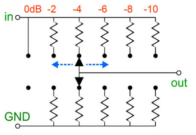
in every position only 2 resistors are in the signal chain - one between input and output and one between output and ground.
core13 said:also does 500 ohm instead of 600 make a difference?
I honestly don't know how much of a difference that makes in this particular circuit. We'd have to measure the frequency response of an actual unit equipped with 500/500 attenuators to find out.
FWIW many builders of my Pultec EQP-1A chassis project used a UTC-A20 on input for their builds (which is 500/500) instead of the Triad HS56V (600/600) with great results.
Phrazemaster said:Hi Martin, if you were to drill holes to fit the Davens, would they be hidden behind the knobs? I can't tell from pictures. If so, it might be nice to have the holes for Davens pre-drilled and countersunk, if they won't be visible no matter what the user chooses.
Just to clarify: there are Daven attenuators with regular threaded bushing as well as Daven attenuators without bushing but with 2 mounting screws instead.
Now in this particular project we have actually 2 front panels: one has a hinge welded to it, is made of steel and powder coated the same color as the rest of the chassis.
The second panel is a very thin anodized black aluminum panel with white silkscreening.
IF I added the 2 mounting holes for the use of above mentioned attenuators, these holes would be in the grey hinged front panel ONLY - covered by the black front panel on top of it.
BUT that means:
1. the screw heads would need to be countersunk completely or the upper front panel won't fit. And all attenuators I found so far don't come with countersunk screws - so that could make it complicated to design the chassis accordingly - you know what I mean?
2. that also means you would have to mount the attenuators before everything else on the front panel - even before mounting the second front panel - which can make it a PITA if you want to change the attenuators...
3. the second front panel is held in place by all pots, switches and screws - I don't know if that would be a problem but right now it's also held in place by the mounting nuts of the attenuators...
Just some thoughts
")
On a different note:
Today I swapped my Daven output attenuator for a Mallory T-PAD and even though I don't like the feel as much as the Daven's, it indeed increases the output by 6db and I think I'll leave it like this for now.
I also started to add some mods without altering the original looks of my unit - I'll talk more about that later
Phrazemaster
Well-known member
Martin, you’ve got a laser-sharp mind. Thanks so much for the extremely clear response.
I think it would be good to give builders the option to have the screw holes if possible; those that don’t need it, won’t use it. I found a lot of Davens without the bushing mount, but with only screw holes.
Also, do you or anyone know if the Davens can be rebuilt? If I find a 20-step version with 1.5DB steps, can I open the unit and change resistors to get 2DB steps?
Thanks,
Mike


![Soldering Iron Kit, 120W LED Digital Advanced Solder Iron Soldering Gun kit, 110V Welding Tools, Smart Temperature Control [356℉-932℉], Extra 5pcs Tips, Auto Sleep, Temp Calibration, Orange](https://m.media-amazon.com/images/I/51sFKu9SdeL._SL500_.jpg)


If it works well, mallory have long shaft, so it would be easy to put a metal plate between the inside panel and the attenuator.. Like a mini third panel on each side. This panel can be fixed by using the holes for Daven . I am not sure it is clear, but it is just like the pots in a chandler limiter unit, or a Neve module. But in this case, only a small plate covering the place needed. All pots can be used with that method if shaft is long enough for all panels
Phrazemaster said:Also, do you or anyone know if the Davens can be rebuilt? If I find a 20-step version with 1.5DB steps, can I open the unit and change resistors to get 2DB steps?
They can be rebuilt, but in that case it'd be very dumb because the 1.5dB/step versions are worth significantly more, and really offer you better control.
As to the earlier questions about T versus ladder, the ladder does not need to be loaded in a bridging environment, while an output T does need a 680R resistive load on the output side. A proper T presents a load to ground around 5K at the first step down, and full gain is actually open, with no loading at all. Most limiters/comps of old use ladders, as did most mixers.
Phrazemaster
Well-known member
Thank-you Doug; extremely informative.emrr said:They can be rebuilt, but in that case it'd be very dumb because the 1.5dB/step versions are worth significantly more, and really offer you better control.
As to the earlier questions about T versus ladder, the ladder does not need to be loaded in a bridging environment, while an output T does need a 680R resistive load on the output side. A proper T presents a load to ground around 5K at the first step down, and full gain is actually open, with no loading at all. Most limiters/comps of old use ladders, as did most mixers.
This is great info and clears things up for me regarding the attenuators. I think i will at first use the Mallory T Pads i already have as well and hopefully get lucky on some Daven's or Shalco attenuators or something suitable at some point. With Raintons unit up and running and already experimenting with alternatives and modifications i can only wait for what he can disseminate to us. I already sourced most of my critical parts, have to start thinking about those can caps now. I realise some of these are multi section but which one is which? Is it too early to ask which cap positions relate to the schematic designations/values. Just to get my head around it. Personally i would use all new caps but i guess this will be thrown to a consensus at some point as to what is available, as Rainton has done in his other project threads.
Looking good
Universal Audio 176 from scratch - a 100% faithful recreation of a legend! even 80% would be great!
Looking good
Universal Audio 176 from scratch - a 100% faithful recreation of a legend! even 80% would be great!
moltenwok
Well-known member
cough-sidechainHPF-cough mod cough
rainton
Well-known member
craig said:I already sourced most of my critical parts, have to start thinking about those can caps now. I realise some of these are multi section but which one is which? Is it too early to ask which cap positions relate to the schematic designations/values. Just to get my head around it. Personally i would use all new caps but i guess this will be thrown to a consensus at some point as to what is available, as Rainton has done in his other project threads.
Yes we have 3 multi-section can caps in this circuit - two of them being located in the PSU. C11 & C8 to be precise.
C11 is a four section cap with 4x 20uf/450V of which 3x 20uf are connected in parallel to give 60uf + 1x 20uf, and C8 is a 2x 20uf/450V.
Both of them are still available and I'll point out where to get them in the BOM later.
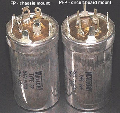
The 3rd can cap is C9 which is 2x10uf and a little harder to come by - especially since the original one was a PFP cap.
Here's a pic so you know what that means:
On the left is an FP chassis mount cap - those kind of can caps are still available new. On the right is a pcb mount PFP can cap which are not being made anymore:
Well this particular cap (C9) is soldered directly to the pcb (you can see it in some pics that show the back of my unit - it's the can cap on the right sticking out through the rectangular cut-out in the chassis)
For the prototype Livingnote and I agreed to keep the original footprint on the pcb, but instead of just putting holes in the pcb to mount a PFP type can cap, Livingnote cut in slots to hold the FP type terminals.
But to be frank mounting that cap was a drag, and we're still figuring out a way to make it easier. Especially it's a lot of extra work to cut these custom slots in every single pcb...
I'll let you know when we did
Anyway we'll include the option to mount 2 regular electrolytics in this spot, so you could always go that route.
I would highly recommend NOT to look for vintage PFP type can caps to use for this project as that's asking for trouble.
On a different note - I'm getting lots of mails and messages of what parts to source etc. You can make it easier for yourself if you wait until I finished a first revision of BOM - then we can discuss further.
One thing many people ask in particular I will try to explain here briefly:
"What are these things here and where can I source them":
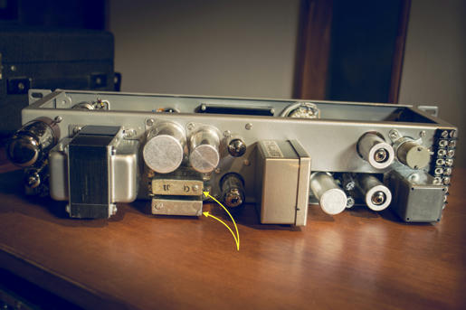
These are oil filled 0.5uf 600V caps (C6 & C7) and extremely hard to find.
Here's a pic of a very early state of my build that shows the terminals of these caps from inside the chassis:
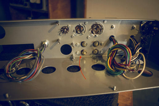
Anyway - there were also many models of original 175b and 176 that had film caps in this spot - mounted inside the chassis with the help of a small turret board and some spacers:
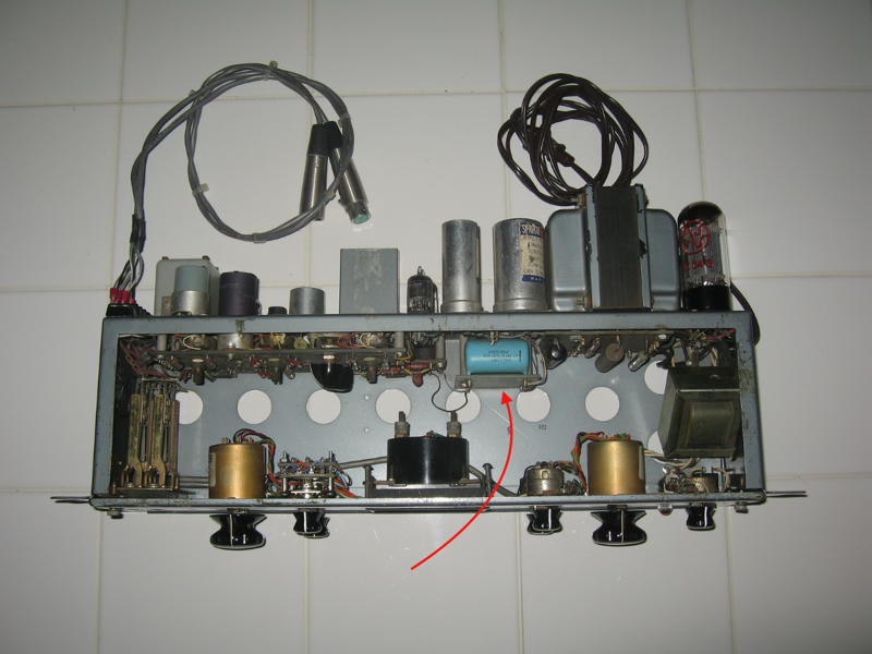
Thus, the chassis doesn't feature the 4 cutouts for the terminals of the oil caps as you can see in this pic:
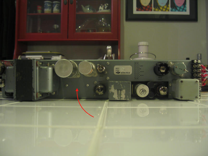
Since these oil filled can caps with the exact physical dimensions needed are pretty much unobtainable and there were original units with film caps instead, I will design the chassis for the use of film caps here and most likely add a turret board to let you mount (whatever) film caps (you like).
So I hope all of you who laid awake at night wondering what these things were and where to get them can now finally sleep again ;D
rainton
Well-known member
moltenwok said:cough-sidechainHPF-cough mod cough
*cough* how to implement *cough*
I read something about placing a switchable 10k log pot between C6 & C7 but then again I read somewhere else that it wouldn't work.
Retro added a variable HPF to their 176 - and as far as I know they used a pot, but does anybody know how they did it?
I figured it could also be implemented by changing the values of C6 & C7 but that wouldn't work with a pot then right...
any idea anybody?
Phrazemaster
Well-known member
rainton
Well-known member
The problem is guys, that they all have different dimensions and that makes it close to impossible to design the chassis for them (fora production run)
The one Phrazemaster posted is smaller than mine and the terminals are closer together.
And the one craig posted won't work at all - unfortunately - since it has the terminals on one side and the mounting brackets on the other side - and apart from that the size appears to be different, too.
The ones I used look pretty much like this:
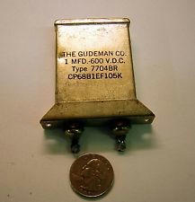
But like I said - since the original units also were available with film caps I wouldn't bother.
I could design the cutouts into the chassis but the possibility that the caps you'll find - if you find any - won't fit is like 90%
And I think having holes you don't need in the chassis doesn't make the end result look any better.
The one Phrazemaster posted is smaller than mine and the terminals are closer together.
And the one craig posted won't work at all - unfortunately - since it has the terminals on one side and the mounting brackets on the other side - and apart from that the size appears to be different, too.
The ones I used look pretty much like this:
But like I said - since the original units also were available with film caps I wouldn't bother.
I could design the cutouts into the chassis but the possibility that the caps you'll find - if you find any - won't fit is like 90%
And I think having holes you don't need in the chassis doesn't make the end result look any better.
Phrazemaster
Well-known member
I just bought some A19's in an eBay auction and will have extras. See the black market if interested.
Mike
EDIT: these may be gone. Still post interest in case sales don't go through, but I got responses in just minutes...
Mike
EDIT: these may be gone. Still post interest in case sales don't go through, but I got responses in just minutes...
UTC A-18 was apparently the primary part here, though either 18 or 19 should work fine.
https://groupdiy.com/index.php?topic=17733.msg207048#msg207048
I too, have one piece for sale in the black market. Looks like Phrazemaster's A-19's are all gone, so hopefully not stepping on his toes.
https://groupdiy.com/index.php?topic=17733.msg207048#msg207048
I too, have one piece for sale in the black market. Looks like Phrazemaster's A-19's are all gone, so hopefully not stepping on his toes.
Phrazemaster
Well-known member
Not a bit. I'm a little disappointed though because in my research I had found the A-19 to be the original. Can't tell from the schematics - at least I can't. My copy is fairly blurry and haven't found a clear copy yet. I found another reference that stated that either one was used.emrr said:UTC A-18 was apparently the primary part here, though either 18 or 19 should work fine.
https://groupdiy.com/index.php?topic=17733.msg207048#msg207048
I too, have one piece for sale in the black market. Looks like Phrazemaster's A-19's are all gone, so hopefully not stepping on his toes.
So what would be the difference between them?
Similar threads
- Replies
- 122
- Views
- 12K
- Replies
- 4
- Views
- 1K
- Replies
- 27
- Views
- 10K