GSSL HELP THREAD!!!

GroupDIY Audio Forum

Help Support GroupDIY Audio Forum:

This site may earn a commission from merchant affiliate links, including eBay, Amazon, and others.
Hello all!  I'm a newbie DIYer but have been a member of this amazing place for a while.  Seems that my ambition for building an SSL clone died off over the past few years with work and school taking up so much time but as I am now unemployed and have a fair amount of free time, I'd really like to finish my clone.
I'm using one of Tat's enclosures without the cutout for the meter and with the sidechain punches...I'm going to put in a "dumby" knob and sidechain input until I get the regular model working and feel comfortable with modding it.  Anyway, time for the questions...I have searched a fair amount and learned a lot but I have several questions that I'd really like to have some clear answers for which I couldn't find within this thread.  I'm sorry for my complete lack of understanding with even the most basic concepts.

1.  I'd like to use simple toggle switches for the power and bypass switches.  I have the lorlin 2 ways but they don't fit Tat's enclosure.  What type of switches, (rating, poles etc) will work for both.  I bought two 3 pole switches rated at 6A @125VAC.  It seems that I would need something else for the bypass as the Lorlin type has 5 solder points.  Is the power switch supposed to be a 2 pole?  Most pictures I see of other finished clones show two wires coming off the power switch.

2.  I bought these nifty LEDs for the bypass and power that have resistors built into them...will the resistors affect operation?

3.  I think I have figured out the wiring for my transformer, but just to be sure, I'd really like to know where the main power switch plays into this wiring.  I've got the Brown / Red to the middle point of three on the mother board PSU input and the Blue and Green on the outside points.  Ground of the IEC to the chassis with the ground from ONE XLR input.  The yellow / red go to Hot and violet / black to N on the IEC connector.  Where does the switch connect to?  Yellow /red to one pole and then to the hot / + of the fuse and then the other side of the fuse to the other switch pole?

4.  Where does the bypass LED hook up to?  Can you add the B meter LED to the "power on" LED point?

Again, I'm sorry for my lack of understanding.
Thanks for providing so much info thus far!
-Phil
 
Can someone tell me the correct eao switch to order for this setup im afraid to order to many choices  How about these http://cgi.ebay.com/ws/eBayISAPI.dll?ViewItem&item=300330372985&ssPageName=STRK:MEWAX:IT

Thanks
pedroplanet said:
loopermc5 said:
Has anyone used this wiring does it work?

THANKS
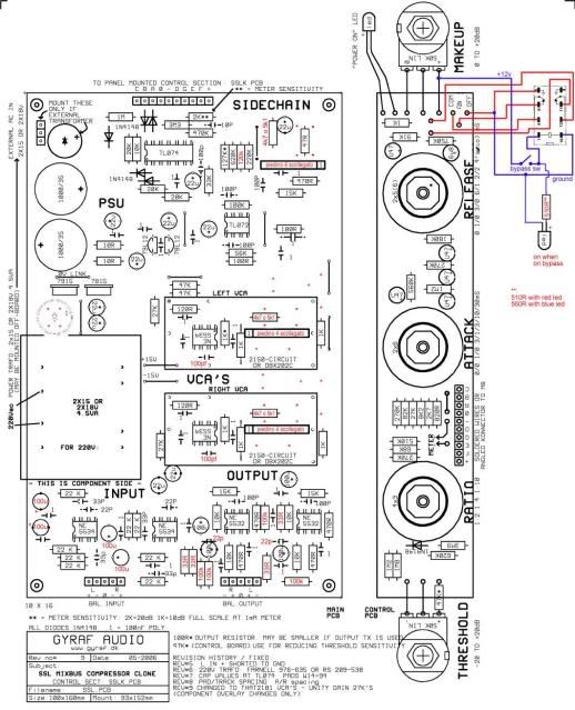
PCB_THAT2180.jpg

where did you find this??
 
loopermc5 said:
Can someone tell me the correct eao switch to order for this setup im afraid to order to many choices  How about these http://cgi.ebay.com/ws/eBayISAPI.dll?ViewItem&item=300330372985&ssPageName=STRK:MEWAX:IT

Can't tell from the describtion what kind of switch this is...
If you want to do the switching just with 1 EAO push button switch you'll need a switch with 3 swithing elements. two should be NO (normally open) and one should be NC (normally closed).
one NO + one NC switching element is used for the actual bypass switching, the other NO switching element is used for tswitching the lamp inside the push button on & off. If you don't care about the lamp a switch with 1 NO and 1 NC will do.

If you do the bypass switching with a relay (as shown in the diagram only don't power it with the 12V rails) a swithc with 1 switching element NO will do.

It sounds more coplicated than it is....;-)
 
Hi everyone,

When I turn the threshold pot all the way down I hear a small 'click' sound(or possibly an electrical arc) come from it, the power led goes out, and the compressor starts distorting. If I add the 47k resistor to the positive leg of the threshold pot (as shown in the schematic) it will not have the "click"/electrical arc problem but I can only just get the unit to compress a little by playing a very loud signal before running out of headroom.


radiance's reply:
Probably a short in the control board connection. What voltage do you measure on the three legs of the threshold pot when you put the wiper in the middle? (without the 47K resistor in place)
I'm having a similar problem yet also on the makeup side.
It passes no audio at FCC, but if you put threshold and makup at 12o'clock and slowly turn makup up, you begin to hear a very distorted signal at about 1'oclock, almost like you were dialing in a distant radio station. Keep going to 3 o'clock and it fades out again. The sound is never clean.
Attack and ratio do not seem to affect the sound.
Meter is not working.
led on daughter board is +12v
Expat's CRC is delivering +21 0 -21 vdc to additional rectifier on main board psu.
Main board has +15.1 -14.8 power.
Expat Turbo is at -11.73 0 +12.12
The thresh pot reads ~24k both sides when pot is centered and all wires are disconnected.
50k makeup pot reads ~13k both sides when pot is centered (wires are connected to board with this one).

Initially I had reversed the TL074 on the turbo board, powered it up a few times, then found the error and correctly placed it, however distortion occurs if turbo is on or not, both channels.

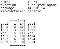
Also can someone confirm pinout?

TL074.jpg


I'm going to bed now, but I wanted to post what I've found so far. I'll go over ssltech's troubleshooting guide tomorrow. in the meantime, if any of my issues sound like something you could help me with to narrow the problem down, let me know. Thank You!'

Edited 12/17 for language clarity.
 
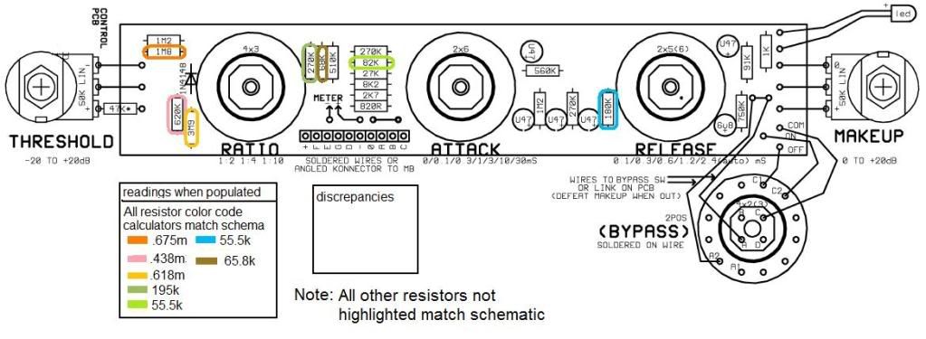
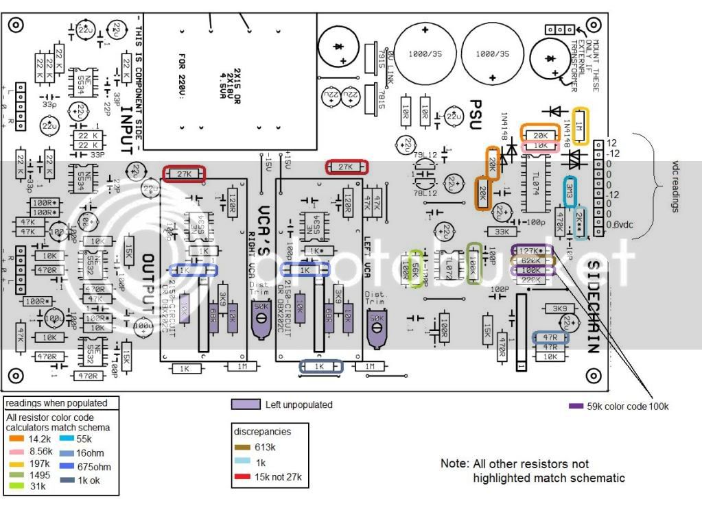
Checked all resistors tonight. I'll look at caps tomorrow, TL and VCA's over the weekend. If anybody has a a min, just scan what i've found, see if anything jumps out at you. I'm pretty sure with the exception of the two 27k's everything is correct, resistor-wise.


GSSLresistortroubleshootmainboard.jpg


GSSLresistortroubleshootcontrolboar.jpg
 
Hey analogical,
did you lift one leg of each of these to check the values of these resistors? Cause if you left them in circuit it is normal for them to "read" some whacky value.....

Mac.
 
hi guys!
i'm a noobie.
i builded my gssl and it doesn't work.i spent all night checking voltages, resistors and capacitors,
and now i'm starting to think i followed the wrong schematics..

my main problem is that my Comp doesn't work. i measured the power voltages on the opamps and they all are
+/-14.89, while i think they must be, at least, +/- 15.  i don't know what to do..
maybe my toroid is wrong? seriously, i don't know what to do..

Input & output 5534 5532 voltages are good
 
pietro_moog said:
hi guys!
i'm a noobie.
i builded my gssl and it doesn't work.i spent all night checking voltages, resistors and capacitors,
and now i'm starting to think i followed the wrong schematics..

my main problem is that my Comp doesn't work. i measured the power voltages on the opamps and they all are
+/-14.89, while i think they must be, at least, +/- 15.   i don't know what to do..
maybe my toroid is wrong? seriously, i don't know what to do..

Input & output 5534 5532 voltages are good


Hows your +-12V rails?
If your rails are right, then your toroid and power supply section is probably right.

What exactly is the problem?  Can you hear audio?  Distorted? Ok, but no compression?  Meter working?
 
analogical said:
Checked all resistors tonight. I'll look at caps tomorrow, TL and VCA's over the weekend. If anybody has a a min, just scan what i've found, see if anything jumps out at you. I'm pretty sure with the exception of the two 27k's everything is correct, resistor-wise.

The 27K resistors at the input to the audio VCA's are required for unity gain.  The 15K value is incorrect.

Also, what schematic are you looking at, and why are you changing so many resistor values?  Changing some of these values is going to give you a screwed up comp. For instance, putting a 59K resistor in place of the 127K ratio resistor is going to get you some messed up ratio values.
 
onlymeeee said:
pietro_moog said:
hi guys!
i'm a noobie.
i builded my gssl and it doesn't work.i spent all night checking voltages, resistors and capacitors,
and now i'm starting to think i followed the wrong schematics..

my main problem is that my Comp doesn't work. i measured the power voltages on the opamps and they all are
+/-14.89, while i think they must be, at least, +/- 15.   i don't know what to do..
maybe my toroid is wrong? seriously, i don't know what to do..

Input & output 5534 5532 voltages are good


Hows your +-12V rails?
If your rails are right, then your toroid and power supply section is probably right.

What exactly is the problem?  Can you hear audio?  Distorted? Ok, but no compression?  Meter working?


voltages on Ins & Outs 5534 & 5532 are good (i think)
i have 12,4 on pins 1 & 8 of 5534s, and zero on everything on 5532, except the +/-  14.8 of course

my problem is that comp doesn't pass signal.  nothing.  (i'm sure it's ON, leds are working)
( i didn't tried on bypass,i'm just trying to keep the circuit simple,so i wired Com to On and the 2 jumpers on the controls pcb)
signal comes and goes thru xlr connectors to pcb (i checked with multimeter and a resistor on every connector's pin)

i don't have a meter, sifam takes at least 10 weeks to ship you one.
is that a problem?


from Mac
Hey analogical,
did you lift one leg of each of these to check the values of these resistors? Cause if you left them in circuit it is normal for them to "read" some whacky value.....
I checked the resistor color bands to confirm that they matched the board, the wacky values I posted to show what they are when 'in circuit', I was thinking that if others don't lift the legs, they may have something to refer to.  
from regularjohn
The 27K resistors at the input to the audio VCA's are required for unity gain.  The 15K value is incorrect.
Also, what schematic are you looking at, and why are you changing so many resistor values?  Changing some of these values is going to give you a screwed up comp. For instance, putting a 59K resistor in place of the 127K ratio resistor is going to get you some messed up ratio values.
I see now that the board I have is Rev7 and the schema is Rev9.   The silkscreen on rev7 asks for 15k.   :-\
As for the resistor values, I diddn't change anything, these numbers were just what I got with them populated. Instead of lifting the leg and checking, I just wrote down what I got 'in circuit', then checked resistor color calcs. If the color bands on the resistor matched the correct value that was silkscreened on the schema, I didn't bother to lift the leg and chance burning out more pads.
I'm starting on the IC's now. Will post voltages tonight, thank you both for your responses.

 
hi guys!
i double checked everything, and i found out  i don't have a -12v rail. maybe the 79l12 is fucked, i don't know that.
how can i check? i mean, i'm a noobie, is there a way to check it with a multimeter?

i didn't study the schematics deep enough,but it seems to me that all +12,4 from pins 1 & 8 of 5534s comes from
+/-15v rails,  and the +/- 12v rails go only to TL072 ,Tl074 and Sidechain VCA;  is all of this true?

thanks
 
pietro_moog said:
hi guys!
i double checked everything, and i found out  i don't have a -12v rail. maybe the 79l12 is fucked, i don't know that.
how can i check? i mean, i'm a noobie, is there a way to check it with a multimeter?

Set your meter to read DC voltages and check the center pin of the regulator in question with the positive lead of the multimeter.  Remember to ground the other lead of your multi, otherwise you will not get an accurate reading.  If you look at the bottom of the PCB you will see a +12v -12v legend close to the 12v regulators.

-Casey
 
i'm not sure
my 79L12  voltages are:

Out:     0,64  (and this is the voltage on all my -12v rail)
In:     -20,3
Com:    0


while my 78L12 volts are:

In:     19,7
Con:   0
Out:   11,91


i don't think this is normal. is it?
 
schematic and pcb layout revision numbers dosn't follow each other. PCB #7 is the latest iirc.

Jakob E.

Thanks Jakob. Just to be sure, If pcb#7 silkscreen says use 15k but schematic says use 27k, follow the silkscreen?
All I found when searching was:
...as designed it couldn t be adjust as unity gain.
so if you want unity gain change 10K trimpot for higher value or the 1K resistor to a 2K or 2K7.
apply a 0db signal 1Kz measured at the L R greg pcb inputs.
adjust the trim so you have 0db at the filter pcb output.
hope it can help
audioforge
response from Digichild: this didnt work for me instead i changed the resistors from the mainboard back from 27k to 15k...

Also something of note, the distortion issue I'm having is identical whether or not the TL074 is inserted or left out...
 
Back
Top