GSSL HELP THREAD!!!

GroupDIY Audio Forum

Help Support GroupDIY Audio Forum:

This site may earn a commission from merchant affiliate links, including eBay, Amazon, and others.
hi, i ve my unit finish evrything work fine , just one thing is strange ,
when i put compression onthe galvomter down left of the zero.
i 've a sifam 1ma and the resistor is 2k ,i tried to change with 3k 4k 5k etc...
but nothing change.
if someone had already this problem.
Thanks
 
yes,
when i make the comp on "ON" the meter goes in the wrong direction and his signal is about -19mA between the wired meter + and and the meter + but when i compress one song it moving fine.
 
livingnote said:
Hey Casio, you might want to try to take it from the top. If your voltages are correct,
see if you can get yourself a probe to go looking for the signal in the individual nodes.

You grab this ol' meter probe and solder it to the hot (xlr pin 2) pin of an XLR and 3 to 1
to ground. Or a simple mono jack plug - stick that into your DAC and monitor to headphones.
Now you can go looking for the signal and where it's not getting through. Cross out
nodes where the signal gets through ok on the schematic and work your way forward.

I know, it sucks when it totally doesn't work, but with your power headphones on you
pretty much always get through...though sometimes the circuit board doesn't have much
appreciation for you left by the time you're done ;)


Thanks so much for the advice, livingnote - at least it's a place to start.

Hopefully I'll have time to do some troubleshooting this week, and will be sure to post my findings.


Best.

 
pearldrum944 said:
I still have a lower signal on the left output.  I have only .02v at the - side of the output XLR (all others are ~3.7v).  I checked the 100r resistor on the board, one side says 3.7v, the other .02v.  BUT!  I found out that my wiring for + and - was backwards for the XLRs on the pcb connectors(I originally mixed up input/output connectors).  Once I swapped around the wires in the connectors to the other side, the resistor that before was testing bad, tests fine!  And now the 100r on the other side of the connector is showing a drop from 3.7v to .02v...?  I have continuity from the 100r to the xlr connector.  

Anyone have any idea about this?  I am absolutely lost.  Thanks again.
 
pearldrum944 said:
pearldrum944 said:
I still have a lower signal on the left output.  I have only .02v at the - side of the output XLR (all others are ~3.7v).  I checked the 100r resistor on the board, one side says 3.7v, the other .02v.  BUT!  I found out that my wiring for + and - was backwards for the XLRs on the pcb connectors(I originally mixed up input/output connectors).  Once I swapped around the wires in the connectors to the other side, the resistor that before was testing bad, tests fine!  And now the 100r on the other side of the connector is showing a drop from 3.7v to .02v...?  I have continuity from the 100r to the xlr connector.  

Anyone have any idea about this?  I am absolutely lost.  Thanks again.

Sorry I don't understand your question really...is the .07V on the + or on the - output from your gssl?
 
ok so i have wired up my transformer secondaries so one wire from each secondary is combined to create an 0v
I know the 0v goes to the middle pin, now does it matter which way round the other 2 go?
sorry if this is a dumb question
 
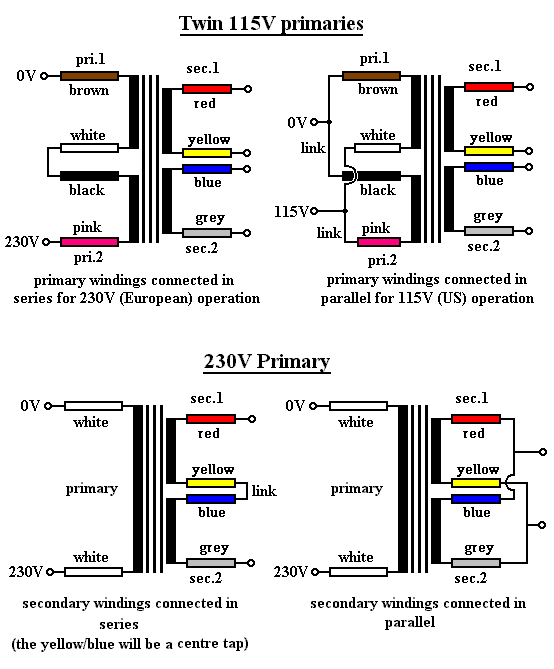
So I googled for toroid wiring and found this neat picture  ;)

We want the left scenario...(upper or lower depending on your primaries)
wiring.gif


Collors will probably NOT match your particular toroid but they'll help explaining.
With your DMM set to AC measure between grey and blue. It should read something between 15V and 18V AC. Between yellow and red it should be the same. When this is the case it's correctly wired.

both DMM & Google are your friend  ;)
 
Thanks roland, i got that far with your explanation over PM.
Now I'm just interested in connecting to the board, I know the linked one (Ov) goes to the middle pin on the board, but does it matter which way round the other 2 go?
 
thanks man.
I just noticed on the right hand side on the control board there is a jumper point, well its really small I'm not sure if i am to jumper this or not.
There is a little A next to one points and A2 next to the other.
Anyone know, shouls i jumper this?
 
radiance said:
pearldrum944 said:
pearldrum944 said:
I still have a lower signal on the left output.  I have only .02v at the - side of the output XLR (all others are ~3.7v).  I checked the 100r resistor on the board, one side says 3.7v, the other .02v.  BUT!  I found out that my wiring for + and - was backwards for the XLRs on the pcb connectors(I originally mixed up input/output connectors).  Once I swapped around the wires in the connectors to the other side, the resistor that before was testing bad, tests fine!  And now the 100r on the other side of the connector is showing a drop from 3.7v to .02v...?  I have continuity from the 100r to the xlr connector.  


Anyone have any idea about this?  I am absolutely lost.  Thanks again.

Sorry I don't understand your question really...is the .07V on the + or on the - output from your gssl?

The - side of the left output is .02v.  I have a voltage drop accoss the 100r resistor before the output connector, and not on any of the other 100r's.  If I switch the + and - wires the resistor is fine, and the other one is bad.  Basically the voltage drop at the resistor follows whatever the - side of the left output is plugged into.
 
pearldrum944 said:
The - side of the left output is .02v.  I have a voltage drop accoss the 100r resistor before the output connector, and not on any of the other 100r's.  If I switch the + and - wires the resistor is fine, and the other one is bad.  Basically the voltage drop at the resistor follows whatever the - side of the left output is plugged into.


Maybe a short in your cable? The one connected to output of the GSSL that is...
 
radiance said:
pearldrum944 said:
The - side of the left output is .02v.  I have a voltage drop accoss the 100r resistor before the output connector, and not on any of the other 100r's.  If I switch the + and - wires the resistor is fine, and the other one is bad.  Basically the voltage drop at the resistor follows whatever the - side of the left output is plugged into.


Maybe a short in your cable? The one connected to output of the GSSL that is...

Would that cause the voltage to drop from one side of the 100r resistor to the other though?  I also have continuity between the 100r and output XLR...I will check though, it does make sense that it would be the cable since the issue moved with the cable.
 
My wire seems fine...but I have 4v output from my 5532 on both pin 7's and a pin 1.  But on the other pin 1 (the one giving me trouble)  I have 3.4v. 

Also, has anyone noticed a discrepancy between the circuit diagram and the component/signal path overlay in that in the circuit diagram there is a 15k resistor between pins 2 and 1, then a 10k between pins 6 and 7, but this is reversed on the overlay and PCB's?  Maybe I'm waay off here.  Does this even matter?
 
pearldrum944 said:
My wire seems fine...but I have 4v output from my 5532 on both pin 7's and a pin 1.  But on the other pin 1 (the one giving me trouble)  I have 3.4v.  

Also, has anyone noticed a discrepancy between the circuit diagram and the component/signal path overlay in that in the circuit diagram there is a 15k resistor between pins 2 and 1, then a 10k between pins 6 and 7, but this is reversed on the overlay and PCB's?  Maybe I'm waay off here.  Does this even matter?

Does not matter. Check all resistor values around the faulty output NE5532...and check for solder shorts...
 
Wow.  Um....right.  My input trims 1/2 on my 192i/o were off...  I switched to hardware insert 3/4 and they are even now.  Thanks for all the help everyone.  As far as I can tell everything is working great right now. 

All I have left to do is research the meter light and what resistor to use.
 
Back
Top