GSSL HELP THREAD!!!

GroupDIY Audio Forum

Help Support GroupDIY Audio Forum:

This site may earn a commission from merchant affiliate links, including eBay, Amazon, and others.
Only took me six months to finish it!
But now it's done and I'm ready to build another one and learn from my mistakes.
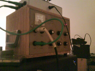
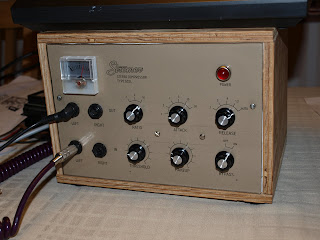
image-upload-44-748161.jpg


P2252632.JPG
 
Hello,
I'm a total newbie here.  I've just started sourcing parts for the gssl and I'm a bit stumped where the ceramic capacitors are concerned.  In the American parts list, they have 22p 100V and 33p 100V capacitors listed...but I can't for the life of me find them anywhere.  I then noticed that on the European parts list, the capacitors are 50V instead of 100V.  Does it matter if the capacitors are 50V or 100V?  The 50V are quite easy to find.  I'd appreciate any advice on the matter :) thanks so much!
 
Hi,
  just fired up a dual GSSL and it works just fine ( except ) " Buzz " that gets louder with make-up gain, when make-up is all the way down / off, I cant really tell if its there or not, but when MG increases, so does the buzz. All functions work correctly and the audio passes cleanly. I have a Turbo board on, non switchable, disconnected and wired as stock and got the same noise, no change. Noise disappears when switched  to Bypass set up on DPDT toggle wired as SSLtech state here http://www.groupdiy.com/index.php?topic=34219.0  Both main PCBs where tested in a working GSSL 1u case unit and worked fine and no noise, so I think the problem is in the control board.  Would very much appreciate it if anyone has heard of this before, or could help this newb out.

littleant said:
Hello,
I'm a total newbie here.  I've just started sourcing parts for the gssl and I'm a bit stumped where the ceramic capacitors are concerned.  In the American parts list, they have 22p 100V and 33p 100V capacitors listed...but I can't for the life of me find them anywhere.  I then noticed that on the European parts list, the capacitors are 50V instead of 100V.  Does it matter if the capacitors are 50V or 100V?   The 50V are quite easy to find.  I'd appreciate any advice on the matter :) thanks so much!
 - I could be wrong, but I think 50v - 63v should be good, the first one I did, I think I had the same problem and used 250v - they work fine but had to get  " creative " in mounting them as to physical size.

I used these in later units   http://www.newark.com/multicomp/mc0805n220j101a2-54mm/multilayer-ceramic-capacitor/dp/46P6469
                                     http://www.newark.com/vishay-sprague/561rtsq33/ceramic-capacitor/dp/69K4621

radiance said:
 
Now THAT's just lovely ...

X2

     Great job akestromer


EDIT - second link now goes to the 33pf cap
 
  Hi Keith,
            I just fired it up yesterday and hooked a 58 up to it from a G9. I think its more  " a buzz (with lots of "Zizzzzzzzz")  "  although I just recieved a CRC board from you, it is for the single 1U unit, but perfboarded the one in this unit as its in a 2U case.  I wont be able to do more trouble shooting until Monday night, but will take the one I made out of the loop to see if there is a change, as well as try and swap control boards from the 1U unit to see if anything changes. Didn't want to have to do that cuz the 1U unit has the SSC.

  Thanks for taking the time, and as always is much appreciated,
                                                                                      Chip


Guys, I am newby here and also from Brazil, so, forgive me for some mistakes...

I just got my GSSL done, with no SC or Turbo board, just the simple GSSL done.

I powered it up and got the led lit, ok, than I fed it with some singal, the VU was alive... but:

Problem 1 - everytime I change the RATIO, the marker on the VU pops to the right very hard... problem!??

Problem 2 - NO OUTPUT (even with the the Makup knob to the maximum)

Also, after powering it down, the thing will not power up again.

Any sugestions??

Thanks!

BTW - this Desktop GSSL that akestromer made is beaultiful. My plan is to make my desktop too.
 
Does anyone still read this forum!?

I firgured out some problems due the configuration around my 2180LBs... problem is... the VU seams and visually feels to be working as it should, but, I have extremely hot output that overdrives my converters totally... in fact, the output itself looks like very distorted/overdriven. Makeup gain or ByPass switch do not work.

Anyone!?


Thanks!

Chuck
 
Hi there,

I have just got my Gssl up and running, and all seems to work beautifully, and sounds great with no audible distortion.
One thing I noticed before I put all the chips in was that I was getting 0.6V on Pin 8 of the Left VCA and 0.25V on the right VCA. I added the chips and thought I'd check the output levels and it seems the left channel is 0.5 dB louder than the right.

I read a few little posts similar to this earlier on, but any tips on where to check and what to check for would be really helpful.

thanks


sorry forgot to mention.... level mismatch is with gssl bypassed and unbypassed!

thanks
 
Just tried troubleshooting..... thinking outside the box... literally.....

one very long xlr was causing the in balance. rock on... my gssl lives!

thanks so much to the incredible amount of information and bordering on genius that exists on this forum. long may it live on!
 
currently building my second GSSL, first time round I used molex crimp headers, but crips were a total PITA, on my second build i opted for the small screw terminals, and they have saved me so much time, the only problem is one of the capacitors gets in the way of the output terminal, anyone have a suggestion to get round this, i know the design was done to fit on the standars size eurocard so some things will be tight,
 
Solder the cap in a more creative way;)

(e.g. little standing above the board, rotated sidewards, whatever, didnt look on the pcb layout right now)
 
Hey guys,

I would like to mod my standard GSSL's with a HPF, is it the super side chain board I need to do it? I've been away from the GSSL for a while so I'm not up together with all the mods..

All the best

Pete
 
Pete, if you want the Thrust filter added go with the super sidechain board. If all you need is a switchable highpass filter, you can go with Greg's HPF board, I think I 've got one laying around that is no longer needed, pm me your adress and I'll send it over, if you like...

cheers, Marten
 
Autophase said:
currently building my second GSSL, first time round I used molex crimp headers, but crips were a total PITA, on my second build i opted for the small screw terminals, and they have saved me so much time, the only problem is one of the capacitors gets in the way of the output terminal, anyone have a suggestion to get round this, i know the design was done to fit on the standars size eurocard so some things will be tight,

Solder it to the bottom of the board, bend to the side if you have clearance issues with the case.

-Casey
 
Anybody have a suitable replacement for TE62063.  Digikey's been out of stock for months and I really want to finish this up.  I'm in New York.

Thanks
 
peteys said:
Anybody have a suitable replacement for TE62063.  Digikey's been out of stock for months and I really want to finish this up.  I'm in New York.

Thanks

try the 62053 or the 62073. I'm pretty sure I've used the 053 with success.

-Casey
 
hey i am just mounting my parts for the gssl and i have 2 questions:

1. On the control PCB on the right side (at the release) there's a 750K resistor. I ordered that one but i just measured it and it's actually 990K. Will this be a big problem? I'm guessing the release time will be affected in some way if i solder it on the pcb.

2. I'm having problems mounting the Potentiometers for Attack & Release. First off I don't know where wich pins should be sitting. I have a PDF from gyraf.dk where i see the PCB frontside + the back with the connectore lines (sorry don't know how they are called in english). On that PDF, looking at the middle pins of the attack, i see that on the bottom left there should be "A" and on the top right there should be "B". On my potetionmeters though, A & B are next to eachother and not on opposite sides. Maybe someone could just tell me where the outside pins start off so i know where to place my "1".

Also I'm not really sure of how to "Program" the Potentiometers. On the gyraf site it says "relocating the washer/locking pin" when taking off the nut.
I opened the potentiometer and inside are too loose metal parts wich i can move around but i don't really have a clue where to move them so i have it correctly.

I think those are the questions for now ;-) I hope that after those parts i'm done and can test the comp

Phil
 
Back
Top