GSSL HELP THREAD!!!

GroupDIY Audio Forum

Help Support GroupDIY Audio Forum:

This site may earn a commission from merchant affiliate links, including eBay, Amazon, and others.
Harpo said:
schrobbelbop said:
...so i connected 15/15V and 0 From ground...

edit: http://www.europe.origin.electrocomponents.com/webdocs/0da0/0900766b80da0cc3.pdf
is my transformer I've now used Vsec/0v connection and ground for 0 on the pcb.
It is a dual secondary winding.
Tie black and yellow secondary wires together (AFTER making sure, the hard to see isolation paint is scrapped off the transformers lead ends :eek:) and take this junction to the center pin on the pcb transformer connection for your 0V. Red wire goes in one of the outer AC holes, orange wire in the remaining outer AC pcb connection, so all 3 holes on pcb are wired.
BTW adding a location to your profile might help to better help you as this is a intercontinental forum.

Thanks! harpo, gonna check it soon. Now I hope nothing is damaged during incorrect wiring! Location added.
 
Changed transformer connection and my gssl WORKS! great!
thanks harpo.

Only 1 thing is not working. the turbo board.

When switched in constant compression. not reacting on audio but voltage from the treshold control.
the turbo vca 2180 is getting VERY hot. power feed is okay TL074 seems okay when swapped with main pcb.

Love this forum and my new born gssl :)
 
schrobbelbop said:
Changed transformer connection and my gssl WORKS! great!
thanks harpo.

Only 1 thing is not working. the turbo board.

When switched in constant compression. not reacting on audio but voltage from the treshold control.
the turbo vca 2180 is getting VERY hot. power feed is okay TL074 seems okay when swapped with main pcb.

Love this forum and my new born gssl :)
congrats, half way there.
The 2180 shouldn't get hot. You put the chip in in the right direction ? (VCA-pin1 towards the pin-headers side / same as VCA-pin8 next to the expat headphone sign)
Turbo board measures +12V at TL074-pin4 and -12V at TL074-pin11 ?
Double-check parts values and orientation and check, the turbo input connects to the correct side of the lifted 47K and returns to the correct side of the 100R on main pcb.
If you made your gssl mode-switchable, the lifted side of the 47K connects to the pole of a maybe SPDT switch and throw side of this switch either returns to the open pcb hole of this 47K resistor for Aarhus-mode or to the input of the turbo board for Oxford-mode instead. 
Leave out R16 for the 2180 as on main pcb, as this 47R connecting to VCA-pin4 is only needed for a DBX2150. (The other 47R of the 470R/47R voltage divider at VCA-pin3 is still needed).
Good luck
 
gyraf said:
xqqxqq said:
gyraf said:
..please specify what you mean by SL911..??
Solid State Logic 9000 series in the SL911 Channel Strip

.. this thread is about the GSSL-clone...?!?


Jakob E.

Thank you!
I have a SSL9K channel strip, I do not know how to give it power, I ask, SL911 What power?+18 -18-24 +48 ?how to connect to the pin?
SL911 audio input and output to connect?
 
xqqxqq said:
Thank you!
I have a SSL9K channel strip, I do not know how to give it power, I ask, SL911 What power?+18 -18-24 +48 ?how to connect to the pin?
SL911 audio input and output to connect?

I think you misunderstood.  This thread is NOT a help thread for all things SSL.
It's ONLY a thread for the Gyraf buss compressor clone.

Nothing in here about SSL9K channel strips.
Start a new thread in the lab.
 
Now the 2180 is not getting hot anymore when i removed the 47R.
But now i have waaaayyy to much compression with turbo mode on.
I had the vca in wrong way, but seems te be okay.


Harpo said:
schrobbelbop said:
Changed transformer connection and my gssl WORKS! great!
thanks harpo.

Only 1 thing is not working. the turbo board.

When switched in constant compression. not reacting on audio but voltage from the treshold control.
the turbo vca 2180 is getting VERY hot. power feed is okay TL074 seems okay when swapped with main pcb.

Love this forum and my new born gssl :)
congrats, half way there.
The 2180 shouldn't get hot. You put the chip in in the right direction ? (VCA-pin1 towards the pin-headers side / same as VCA-pin8 next to the expat headphone sign)
Turbo board measures +12V at TL074-pin4 and -12V at TL074-pin11 ?
Double-check parts values and orientation and check, the turbo input connects to the correct side of the lifted 47K and returns to the correct side of the 100R on main pcb.
If you made your gssl mode-switchable, the lifted side of the 47K connects to the pole of a maybe SPDT switch and throw side of this switch either returns to the open pcb hole of this 47K resistor for Aarhus-mode or to the input of the turbo board for Oxford-mode instead. 
Leave out R16 for the 2180 as on main pcb, as this 47R connecting to VCA-pin4 is only needed for a DBX2150. (The other 47R of the 470R/47R voltage divider at VCA-pin3 is still needed).

Good luck
 
I had the vca in wrong way, but seems te be okay.

Don't count on it - a blown (shorted) VCA could act like this.

I've never seen any of these VCA's surviving reversing the pins.

Better check it by moving it to audio-path and checking that it still varies gain correctly.

Jakob E.
 
gyraf said:
I had the vca in wrong way, but seems te be okay.

Don't count on it - a blown (shorted) VCA could act like this.

I've never seen any of these VCA's surviving reversing the pins.

Better check it by moving it to audio-path and checking that it still varies gain correctly.

Jakob E.

the vca is also woringin the audio circuit.
I guess I must replace some resistors in the turbo pcb cause the desing is based on the 2150 but is comming with a 2180B but which one?!? its a diffrent setting then the audio vca's i guess
 
regularjohn said:
xqqxqq said:
Thank you!
I have a SSL9K channel strip, I do not know how to give it power, I ask, SL911 What power?+18 -18-24 +48 ?how to connect to the pin?
SL911 audio input and output to connect?

I think you misunderstood.  This thread is NOT a help thread for all things SSL.
It's ONLY a thread for the Gyraf buss compressor clone.

Nothing in here about SSL9K channel strips.
Start a new thread in the lab.

Thank you  very much!


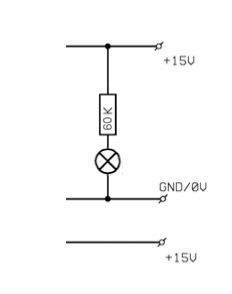
Incandescent lamps should be run directly from the power trafo secondary.  I'd use a 2W resistor at least.  To figure out the value, use ohm's law.

Thanks for your reply regularjohn,
apologies for asking silly questions..... how would I apply ohms law to this situation.
would I be working between the +15v and 0v
rather than between +15v and -15 V (like the schematic shows with the meter light?)
I guess I'd be trying to reduce the 15v to around the 6.3v that the lamp requires?

Thanks in advance!

 
ummmdan1 said:
Thanks for your reply regularjohn,
apologies for asking silly questions..... how would I apply ohms law to this situation.
would I be working between the +15v and 0v
rather than between +15v and -15 V (like the schematic shows with the meter light?)
I guess I'd be trying to reduce the 15v to around the 6.3v that the lamp requires?

Thanks in advance!

There is no negative voltage on the power trafo secondary.  There's +15VAC, 0V center tap, and +15VAC. 
Put the resistor on one of the 15V secondaries, and the other end of the resistor on the jewel light.  And then the other side of the jewel light to 0V.
 
There is no negative voltage on the power trafo secondary.  There's +15VAC, 0V center tap, and +15VAC. 
Put the resistor on one of the 15V secondaries, and the other end of the resistor on the jewel light.  And then the other side of the jewel light to 0V.

I see, that makes sense!
this is the post I mentioned I had seen before:

hey can anyone help me on this, I would like to have a 6.3V Pilot Light instead of the power status led on my gssl and I am not quite sure on how to hook it up.
possibility #1:
get an extra transformer 230V prim / 6V sec
possibility #2:
no extra tranny, take one of the 15V secondaries of existing power trafo and wire a resistor in series with the lamp. The lamp I have around here says it will consum
180mA. Any suggestions?
How do I calculate the correct value for the resistor, is it R = (15V-6V)/0,18A - I have a feeling this is not the way to go, especially since I will be using one of the
secondary windings more than the other... any help really appreciated!
Title: SSL HELP THREAD!!!
Post by: gyraf on July 13, 2005, 06:25:34 am
Quote
is it R = (15V-6V)/0,18A
Yes. 50 Ohms calculated. You may want to run the lamp at under-voltage to prolong life - in that case make the resistor 68R or even 100R. make sure to properly ca
power dissipation and size the resistor for this!
And make sure that your power transformer has the needed 180mA to spare for the light..
Jakob E.


So I have a similar 6.3V lamp which is rated at 0.15A so I'm guessing I would use a similar calculation to the one above:
R = (15V-6V)/0,15A
R = 60 Ohms

how would I go about taking into consideration the power dissipation of the resistor as Gyraf mentioned?
Also I take it that I would need to connect the lamp in parallel?

Thanks again....

 
Hey guys, my GSSL is running great, I can hearly detect any noise, although I did get some hum, but I fitted the CRC board and the hum problem is almost non-existant now, my question is, how does the CRC board work, I know its a rail filter that reduces ripple, but what causes the ripple and how does this create the hum.

Second question, I didnt bother to ground my Inputs and Outputs, now I was going to link the ground on all of the in & out sockets to the mains ground on my IEC socket (im in the UK) but is it worth doing, as i said before i dont detect any noise, could this be because my audio interface is already grounded and this is connected to the GSSL, please tell me if I am doing something dangerous here?
 
ummmdan1 said:
how would I go about taking into consideration the power dissipation of the resistor as Gyraf mentioned?
Also I take it that I would need to connect the lamp in parallel?

P=I*V  Power = Current x Voltage

the lamp should be connected as i stated in my earlier post.
 
Thanks regularjohn,

So just to recap, am I right in thinking that you recommended a 2W resistor by calculating the power usage of the bulb with P=IV?
and is it correct that the resistor value is calculated like this:
R = (15V-6V)/0,15A
R = 60 Ohms

just out of interest why in this case would the V in this case 15V-6V?

So would a 60 Ohm 2W resistor be the best thing for the job?
connected like this:
4503323703_99a026b4ba_o.jpg


Thanks

dan
 
Thanks Jakob,

I'll do that. I think I now understand how ohms law is applied in this situation, so if I want to drop the voltage to around 5V the voltge drop would be 10V hence the 10V/0.15A = 66ohms
so may use a 68ohm resistor.

And the power dissispated by this resistor would be the voltage drop  10.2V x 0.15A drawn by the lamp = 1.53W

so a 68R 2W resistor! 

And it seems my 25VA powersupply should be ok to supply the extra 150mA


I think I'm just typing out aloud! To clarify things to myself!

 
gyraf said:
Don't use the regulated voltage for lamps (unnecessary load which heats the regulators) - use the AC coming from the power transformer directly.

Jakob E.

I think those are the power trafo secondaries in the diagram as there's two +15V sources.


Good work, ummmdan1! 
 
Thanks Guys!
Just need to try that, get the front panel etched, and MK1 is done....
then time for MK2 for my brother!


then probably some 1176s!

wow.... this is addictive!

regularjohn, I just realised that you are the mad scientist who made the 22 channel ssl I saw a few weeks back!

that is insane!  ;)


Thanks for the help, much appreciated.

 
Back
Top