wthrelfall said:
Hey Udo,
It's not Scott, it's William, we already know each other from the u87 clone thread ;D
Pardon me William,have swapped names,too many people at the moment.
wthrelfall said:
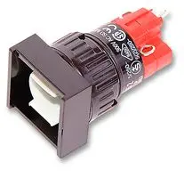
the switch I believe is momentary - here's the data sheet http://products.eao.com/media/technische_daten/BR31_General_technical_data.pdf
Believing is not knowing,hahahaha.....
So if it is momentary you just have a switch function as long as you press the button.
Latching is when you press once for switch function and then press again to release it (on-off-on-off-on-off-on-off-........).
wthrelfall said:
as for the 'true bypass', yes, if it's easy?
It depends.A good solution is using relays in both cases.You want 2 for each channel and a fallback diode supplied by a switched voltage.
With latching switch it´s easy to build even on veroboard.Will have a look for an easy drawing over the weekend,will have it somewhere-if that´s your case.
With momentary switches you want a piece a logic in between switch and relays.
There are some solutions arround here,do a search.
From expat audio (Rochey) I can recommend his differential switch board in combination with his controller and pic (there´s a good description in the manual).Controller is for 3 buttons,just connect what you want:
http://www.expataudio.com/expatshop/index.php?act=viewProd&productId=10&ccSIDab479c27e66aa7ff6e70082511e3b6f4=6a5d7cb054bf846f64f9f5366206632b
From Igor there´s his bypass relay boards and his universal switch board controller,but it´s for 8 buttons and has several logic ways to choose of,therefore a bit overkill:
http://www.ij-audio.com/store/logicutility/
Easiest way is using a latching switch!
Hope to have helped,
Udo.


")