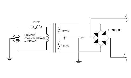
[quote author="radiance"]one +15 tap goes to hole 1, and the other +15 tap goes to hole 4.[/quote]
[quote author="rrs"]So is red and purple +15?[/quote]
Hopefully you didn't hook them up this way.
The transformer you have doesn't have a center tap, just two similar windings for the secondary voltages, each delivering nominally 15 volts. You tie them together in series to create a "center tap" just as you stated in an earlier post by tying red and white together (or in your case soldering them to the two middle holes as radiance suggested).
If you hook up red and purple to the outside pads it won't work. Solder the yellow wire to one of the pads that goes to the bridge rectifier. Solder the red and white wires to the middle pads that are connected to each other and to ground. Solder the purple wire to the remaining pad that goes to the other side of the bridge.
I think the reason no data comes with the transformer is that all the info you need is printed on the side of the transformer itself. But the 2005 paper catalog has a diagram on page 131.


