GSSL HELP THREAD!!!

GroupDIY Audio Forum

Help Support GroupDIY Audio Forum:

This site may earn a commission from merchant affiliate links, including eBay, Amazon, and others.
ok

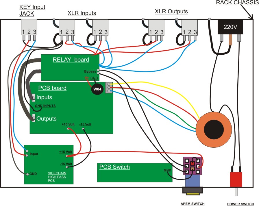
The noise is not cause by the toroid transformer, I move it but stil have noise.

In fact I'am wondering if it's not cause by the SSL highpass filter from Greg.

I put the Ground of the JAck, send , return to the star ground and did the same to the ground of the SSL high pass filter.

I'am wondering too if I have to use Shielded cable for the Relay board


Hey DAX, you 're not from audiofanzine??
 
Greg,
Thanks for responding :thumb:

After HOURS :evil: of troubleshooting I found it has nothing to do with the main circuit board... it's the control panel. I still don't know what but I'll find it. I didn't look there because it had been working fine & I didn't do any work there or even remove it... BUT, not that it's a big deal, I found that the unit with the 218x VCA's has a negative voltage everywhere from the output electro cap right after the 1st 5534's thru the 15/27k resistors, thru the summing resistors up to the sidechain VCA & the one with the 2151's has a POSitive voltage in those spots. When I was poking aroud trying to find why the Threashold was way off I noticed this & thought it was a problem but it ends up that it's NOT :shock: I finally pluged the board into the working (corectly) units front panel & it kicked ass :green: .

So, the voltage difference sidetracked me & must be ok. It was the front control board the whole time.

I still would like to see if anyone else is getting a positive or negative DC voltage in those area's. It could be the different VCA's or the distortion trim circuit being there or not... who knows.

I think my new quote will be "Solid state ain't easy to troubleshoot"
 
Just a question here. I know that the Sidechain is just a high pass filter to affect the way the compressor behaves but what does the TRUST mod do?

Jim
 
So excited I finally finished my first SSL.... (please excuse my newbieness)
When I test voltage I get 9.4V instead of 15 V.
Any ideas why?
I'm using the MT2086 from Jaycar. Wired with yellow on Pin 1, red- pin 2, white Pin 3, and Purple Pin 4.
What other test sould I perform before inserting VCAs and likes?

Thank you!!!

Excited Newbie.
 
I Post a thread "SSL comp noise due to The Bypass LED switch"

I put the diagram here, (better place ) of my Mounting of the SSL.

I have a noise ( 100Hz or 200Hz ) when I put the Makeup at MAX, When I put a 0Db signal, the noise is at very low volume but I'm afraid that when I will use my SSL on big system,, the noise will become listenable.

I'd like to know If I made something wrong,:roll:

Thanks if you can take time to watch this :


SSL%20Plan.jpg
 
Audioguy where did u connected it???

check for shorts
and also check id 7812 and 7815 connected right way

i had simular problem with negative voltages
7912 was connected wrong way
 
Hey Guys,
Thank you so much for getting back to me...
This has been driving me crazy.
The transformer is from Jaycar MT2086 .
Tried connecting to both locations on PCB. now it's at the corner/"external transformer" spot.
I connected the yellow and white together to form center tap (these are the "0" wires) then purple and red go to the extremetie of the connector.
I get a reading of 8.47V from testing yellow/white (connected together) and purple .
and a reading of 8.47V from yellow/white(connected together) and red.

My 78L12 and 79L12 seem correct. Flat part facing in.
I have not installed VCAs or connecteted XLRs, or ground.

I've checked soldering and it lloks good. Haven't gone through to verify if components are all a right location but I did check and recheck as I stuffed the board.

Of course this all happens when I need this SSL to do a mix with a looming deadline..... please help me save $$$ and not have to go buy a stereo comp!!!!

Thanks guys!

AudioguyII
 
mathflan, what is your opinion about the star point you are using? I would, if i were you, i would take a thick piece of green-yellow covered copper cable and strap the grounds together at the point on the left of the IEC plug and not at pin 1 of the first XLR in. strange (in my opinion) is that you didn't ground the key in directly to chassis like the xlr's, but to pin 1 of the first XLR. This is not making sense to me at all but maybe i'm just blocked at the moment...

I've not looked too long on your diagram, so maybe i overlooked something someone else will find...

If you just want to find out, if the grounding scheme is the source of noise or the relay boards, i would simply groundlift (only) the in's completely for troubleshooting and listen again. Is the noise/hum still remaining? what relais are you using?

Kind regards and successful troubleshooting :thumb:

Martin
 
HI smallbutfine, Thanks for the answer.

In fact the KEy input I use is a JACK connection with plastic lug so I have to connect the Pin 1 of this JACK to the star grounding.

In fact my problem is that My XLR are connected to the chassis by themselves when I screw them.
Perhaps I have to Put some scotch around XLR LUG so as to BE not connected to the chassis.
By doing that, I could Connected the Chassis of the XLR at only ONE point.

I Tried a lot of thing to See where the noise come from, But I don't have disconnect the Relay board, I'll try...

I use MT2 AXICOM, TYCO
 
[quote author="AudioguyII"]Hey Guys,
Thank you so much for getting back to me...
This has been driving me crazy.
The transformer is from Jaycar MT2086 .
Tried connecting to both locations on PCB. now it's at the corner/"external transformer" spot.
I connected the yellow and white together to form center tap (these are the "0" wires) then purple and red go to the extremetie of the connector.
I get a reading of 8.47V from testing yellow/white (connected together) and purple .
and a reading of 8.47V from yellow/white(connected together) and red.

[/quote]

I had this wrong when I first built my first GSSL. I have the same jaycar toroid.

I've got it wire:

red/white tied together for - 0V (middle)
purple - 15V (outside pin)
yellow - 15V (outside pin)

This should work.
 
Now I'll ask my own question....

On the gssl pcb it's marked (in the area for pcb mounted toroid) that a 4.5VA toroid will do.

I've got the above mentioned MT2086 toroid which is a 15v-0-15v 20VA. Is it safe for me to assume that if the gssl only requires 4.5VA I'll be able to power 2 gssl's with this one toroid?

Also how might I go about calculating if a PSU pcb (in this case Keith's SSL 9K PSU pcb (thanks Neeno for the idea)) will handle 2 gssl's?

Thanks in advance

Steve
 
Thanks BladeSG,

I also realize I just made a huge error. I live in NY , USA 120V . Not 240V input. I thought this transformer was able to handle all input. So I think I'm only getting half due to this.
I connected it in series and got 16.5V output.... so..... After thinking about it ... I have a few of these transformers. So I took two... I connected their respective red and white together , connected the 2 yellow togther from the two, which leaves me with 2 purple at 16.5V.
I connected the 2 yellow to center tap and the two purples to the live extremities. I finally got 14.9V and -14.9V on my 15V rails, but I get -20V on my 12V rail, and now my LED doesn't light up. It did before when I got 10V on the 12 V rail.
What am I doing wrong....
I've searched the thread but can't find my solution...
Please help.

AudioguyII
 
i got a gssl from a friend, he couldnt make it work. i found 7 solder bridges and some resistors with the wrong value.

fixed it, powered it up but no work.
i read +0,6 volt on the positive +15Volt rail and -9,79 on the negative -15 rail. couldnt find any further solder bridges, ac on secondary of the trafo is ok.
are the regulators gone?

any help appreciated,
max

edit: just found out that the original trafo, which supposed to have 2x18 volt, gave me 28 volt AC unloaded. did this fry the regulators?
 
Actually the power trafo on the GSSL is 15-0-15, not 18-0-18. If you're getting 28-0-28 you'd be dissapating alot of heat and the regulators might be toast, so a regulator swap is not be a bad idea. Are the regulators measuring a short or open circuit?

@Audioguy, I'd recommend getting the correct power tranny for 110/120 before proceeding.
 
[quote author="BladeSG"][quote author="AudioguyII"]Hey Guys,
Thank you so much for getting back to me...
This has been driving me crazy.
The transformer is from Jaycar MT2086 .
Tried connecting to both locations on PCB. now it's at the corner/"external transformer" spot.
I connected the yellow and white together to form center tap (these are the "0" wires) then purple and red go to the extremetie of the connector.
I get a reading of 8.47V from testing yellow/white (connected together) and purple .
and a reading of 8.47V from yellow/white(connected together) and red.

[/quote]

I had this wrong when I first built my first GSSL. I have the same jaycar toroid.

I've got it wire:

red/white tied together for - 0V (middle)
purple - 15V (outside pin)
yellow - 15V (outside pin)

This should work.[/quote]
what a funny coincident. It was my main error, too! Now all voltages are fine! Learning by doing :oops:
I've found the solution on page 40 of this thread.
 
thanks greg !
already replaced the transformer with 2x15v. the regulators do not measure a short, nor do the voltage lines.
its much more difficult to trace something you didnt build yourself...

edit: found out that the voltages are ok when i lift the -15v wire bridge next to the two 47k resistors. resistance to ground is 800R at that point.
 
Hey Greg,
Thanks, I wish I could find a place that has them in stock... if you know of somewhere, I'd appreciate it. Digikey is out.
So using two wouldn't do the trick?
 
Back
Top